Introdução

Follow this guide to replace an Expansion Bay Module, i.e., an Expansion Bay Shell or a Graphics Module, in your Framework Laptop 16.

Depending on your configuration, you may only need to remove the Touchpad Module and the keyboard to access the Expansion Bay. This guide shows removing each Input Modules to include all possible configurations.

If you're upgrading to a new Graphics Module, make sure your BIOS is up to date with the latest version before swapping the modules.

  1. FyZqYQXlGGSUVdfO
    • Unplug all cables and fully shut down your laptop.

  2. bpMHQhFddpbbE5c4
    bpMHQhFddpbbE5c4
    G1ZKNGUFENLOYu3K
    mOP6TMapXCANPZFK
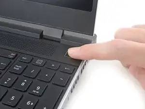
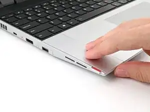
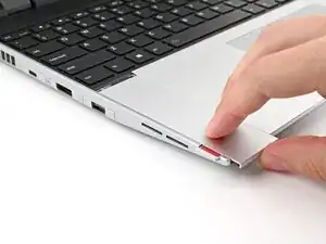
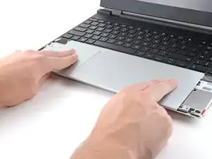
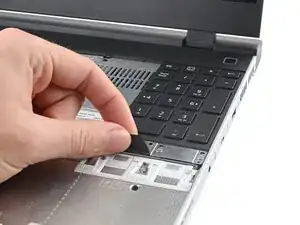
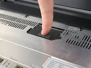
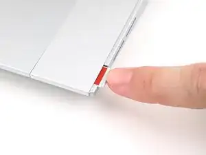
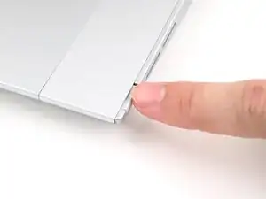
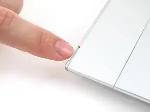
    • Use your fingers to slide the Touchpad Spacer toward the bottom edge of the laptop and unclip it.

    • If you're having trouble, check if the corresponding Input Module latch is properly unlocked.

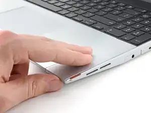
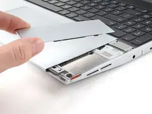
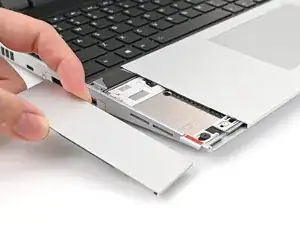
    • Lift the Touchpad Spacer off the laptop and remove it.

  3. oEqip25KTEF2gXZt
    oEqip25KTEF2gXZt
    teuRGEDSLRjVVpId
    mbydNVpAcqSPltCM
    • Repeat the same procedure for the other touchpad spacer.

  4. wpTjqyCvB2wHlNbJ
    wpTjqyCvB2wHlNbJ
    IsFbHVdd3uX4gPbf
    teReJWIbcCJhn3OH
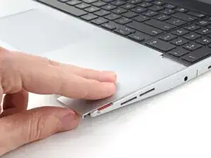
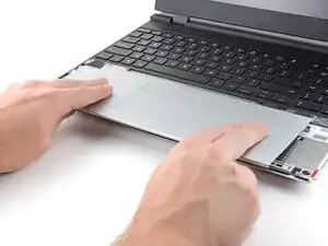
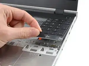
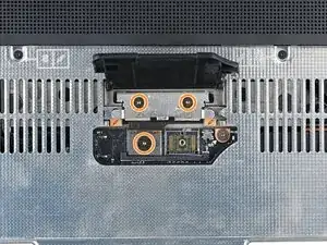
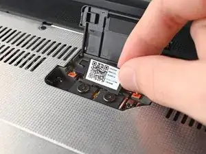
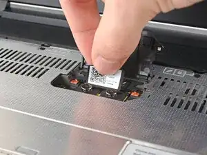
    • Use your fingers to slide the Touchpad Module toward the bottom edge of the laptop and disconnect it.

    • If you're having trouble, check if the Input Module latches are properly unlocked.

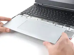
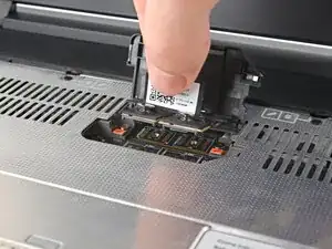
    • Lift the Touchpad Module and remove it.

  5. WXjcPFl2MgDiX2PZ
    WXjcPFl2MgDiX2PZ
    PojU1s2ZQqyfYBvO
    YlWkflmfJPHDuZov
    • The keyboard is held in place with strong magnets. Apply gradually increasing force to avoid having the keyboard violently eject.

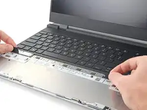
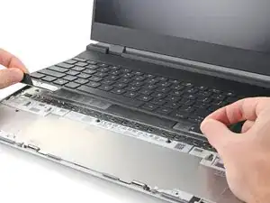
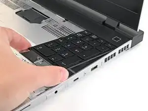
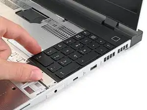
    • Grip the two pull tabs along the bottom of the keyboard and lift until its magnets release.

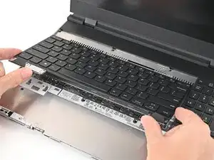
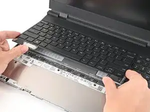
    • Remove the keyboard.

  6. hesMM66MFJtTfvCZ
    hesMM66MFJtTfvCZ
    3ZJ4rrrJTvR22eiV
    WesxvpHZwQSNZ3fK
    • Your Input Module(s) might be different, but the procedure to remove them is the same.

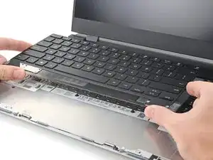
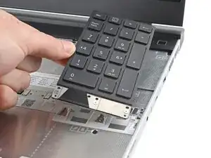
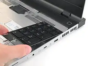
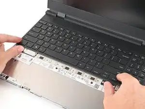
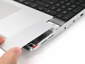
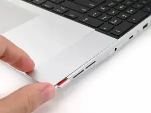
    • Grip the pull tab at the bottom of the Input Module and lift until its magnets release.

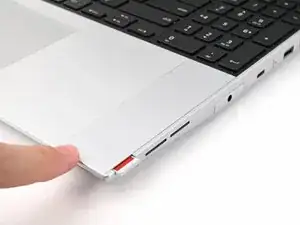
    • Remove the Input Module.

    • Repeat for any remaining Input Modules.

  7. BHwA1RJF1lpIAq4e
    BHwA1RJF1lpIAq4e
    VkpLUbh4wtSFIZ2u
    • Lift the interposer door by its black pull tab and let it rest upright.

  8. oKdJHon6nNCIm1ii
    oKdJHon6nNCIm1ii
    Y5pjOulyPVDGZair
    Dx6pYosnUoQxCI4K
    • If you have the Graphics Module installed, your interposer will have four screws. If you have the Expansion Bay Shell installed, you'll have three screws instead.

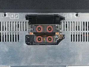
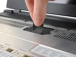
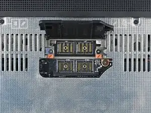
    • If you have the Graphics Module, use your Framework Screwdriver to loosen the four captive T5 Torx screws securing the interposer.

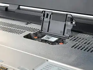
    • If you have the Expansion Bay Shell, use your Framework Screwdriver to loosen the three captive T5 Torx screws securing the interposer.

  9. KqXx1rITOYMfOEeI
    KqXx1rITOYMfOEeI
    EgXNiThu5ZAp2qo1
    • Lift the interposer by its pull tab and remove it.

  10. 1xM31Q5HLnOx22yi
    1xM31Q5HLnOx22yi
    BFNZQlRYjBrJIHOJ
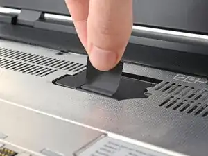
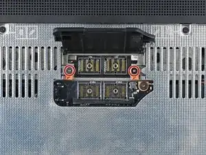
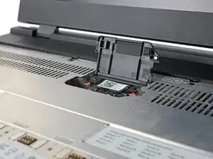
    • Use your Framework Screwdriver to loosen the two captive T5 Torx screws securing the Expansion Bay Module.

    • Close the interposer door before continuing.

  11. LD4vR4HCV1GgbgfH
    LD4vR4HCV1GgbgfH
    qZQIOkPbUWX5wfYK
    C2BItTmGoSeimSuN
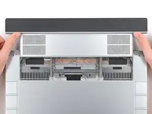
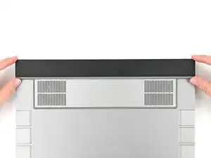
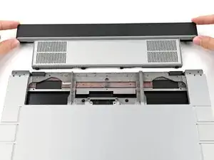
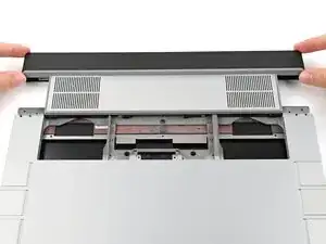
    • Close your laptop and flip it over.

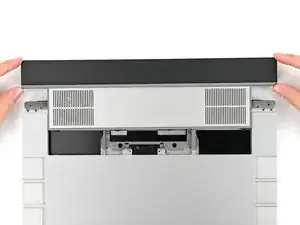
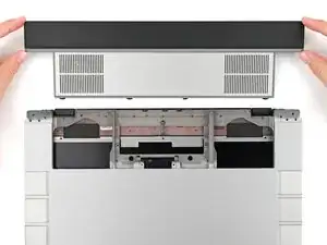
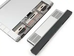
    • Slide the Expansion Bay Module out of the laptop and remove it.

    • The module should slide out easily. If you feel any resistance, check that the screws holding it in place are fully loosened.

  12. yAqjOcYW4FxBfQJa
    • Congratulations on completing disassembly! The remaining steps will show how to reassemble your Framework Laptop.

  13. P3glQ1GTsPkGyH2M
    P3glQ1GTsPkGyH2M
    d32mDZehfiKIfDdr
    • Lift the interposer door by its black pull tab and let it rest upright.

  14. D6OTWEhxRXGNdkN3
    D6OTWEhxRXGNdkN3
    eyC4w4cXsUY1pGO2
    ny2MDHPvLAEQtmsl
    • If you have the Graphics Module installed, your interposer will have four screws. If you have the Expansion Bay Shell installed, you'll have three screws instead.

    • If you have the Graphics Module, use your Framework Screwdriver to tighten the four captive T5 Torx screws securing the interposer.

    • If you have the Expansion Bay Shell, use your Framework Screwdriver to tighten the three captive T5 Torx screws securing the interposer.

    • Close the interposer door.

  15. EgXNiThu5ZAp2qo1
    EgXNiThu5ZAp2qo1
    KqXx1rITOYMfOEeI
    • Place the interposer over its spot between the Mainboard and the Expansion Bay.

    • Depending on if you're installing a Graphics Module or the Expansion Bay Shell, the interposer should be oriented so either rubber grommets or metal tabs cover the Expansion Bay screws.

  16. 1xM31Q5HLnOx22yi
    1xM31Q5HLnOx22yi
    K2msUAJei2QOCFTF
    • Use your Framework Screwdriver to tighten the two captive T5 Torx screws securing the Expansion Bay Module.

  17. VBbHTLV1DNAf1do2
    VBbHTLV1DNAf1do2
    ZOX4NVApgvEBKRiI
  18. JyccFC2cavJAQkw2
    JyccFC2cavJAQkw2
    UBPFtlfVJwD5MG4C
    qDoJmL3yEaNiGyLv
    • Your Input Module(s) might be different, but the procedure to remove them is the same.

    • Align the top edge of the Input Module with the top edge of the laptop.

    • Lay the Input Module on the laptop and let the magnets pull the keyboard into place

    • Make sure the Input Module is seated properly on its alignment pegs and sits flush with the edges of the laptop.

    • Repeat for any remaining Input Modules.

  19. 2oPYqKStliPhyMNB
    2oPYqKStliPhyMNB
    Sa6jykktBZSuiFBK
    mSXYbDZf6nqTloeB
    • Align the top edge of the keyboard with the top edge of the laptop.

    • Lay the keyboard on the laptop and let the magnets pull the keyboard into place

    • Make sure the keyboard is seated properly on its alignment pegs and sits flush with the edges of the laptop.

  20. txabwTJGUoQxRsfP
    txabwTJGUoQxRsfP
    oHknFQArjUvTUTFW
    • Place the Touchpad Module flat on its cutout so its clips are properly aligned.

    • Press the Touchpad Module down and slide it into place so it lines up evenly with the bottom edge of the laptop.

  21. YtqHYbylGARTxNWj
    YtqHYbylGARTxNWj
    cn3jxBl4L54daGYU
    lDt3Lk11ppl6IDoJ
    • Place the Touchpad Spacer over its spot on the laptop with the bottom edge overhanging slightly.

    • Slide the Touchpad Spacer towards the top of the laptop to secure it.

    • Repeat the same procedure for the other Touchpad Spacer.

  22. tiRuQKtLf5CEeB1o
    tiRuQKtLf5CEeB1o
    KIADBeXsLRFTqWIS
    IkUHVd6uW3V4NXVd
    • Push the Input Module latches back into place to lock them.

  23. eS3bQOMDJ51BWdP5
    • If you're installing a new Graphics Module, check out this page to install the associated driver bundle.

Conclusão

If you need help, contact Framework support.

Alex Diaz-Kokaisl

Membro desde: 16/01/22

227430 Reputação

0 comentários