Introdução
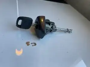
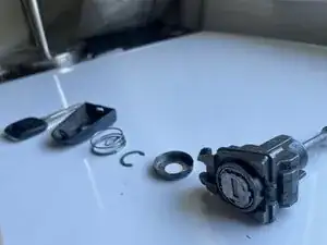
This guide will help you remove a broken pin from a Toyota Door Lock Cylinder, this is useful if you cannot move your key to the left or right to lock the doors or to unlock. This guide is also useful if you do not want to call a Locksmith to avoid paying costly repair services. We provide careful instructions so you do not risk losing any parts or to be worried if you are doing the disassembly incorrectly. This is a guide is a step-by-step process that includes warnings and tips to induce careful instruction on how to disassemble, removal and assembly of the Toyota Door Lock Cylinder.
Ferramentas
-
-
Remove the Plastic Lid
-
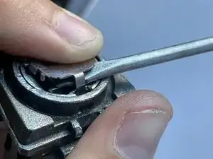
Insert a flat-head screwdriver between the metal latch and the plastic cover and gently twist to release/pry off the latch—avoid excessive force to prevent cracking the plastic
-
-
-
Remove the Metal Ring Holder
-
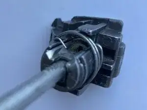
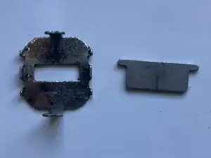
Turn the door lock over and locate the metal ring on the back. This ring clamps onto the metal depth bracket, holding the lock assembly in place.
-
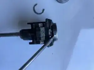
Use a flat-head screwdriver to lift the ends of the metal ring, then slide the ring outward along the sides of the door lock to release it.
-
Repeat the process on the other end of the ring, pushing it to the left to fully remove the ring and allow flexibility when removing the cylinder.
-
Pull the ring and set it aside for re-assembly.
-
-
-
Remove The Metal Cylinder Holder Washer.
-
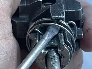
Look for the view in the picture
-
Use a screwdriver to gently pry one end of the washer or ring forward to loosen and remove it.
-
Do the same for the other end. And remove the piece on the side for re-assembly.
-
-
-
Remove The Metal Cylinder Holder Washer
-
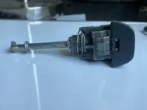
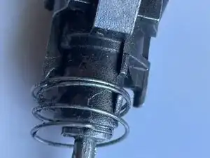
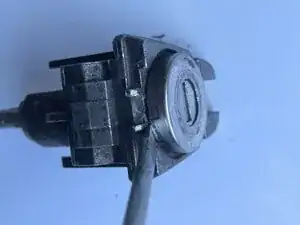
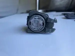
Locate the front view of the door lock—the side where the key is inserted.
-
Use a screwdriver to gently pry up one end of the metal lid and lift it off the door lock.
-
Pry the metal lid off the door lock and set it aside for reassembly.
-
-
-
Remove The Door Key Hole Metal Parts.
-
Side Note: This procedure requires moderate force and patience. The metal components clamped to the sides may be difficult to remove and could remain stuck until gentle but firm pressure is applied.
-
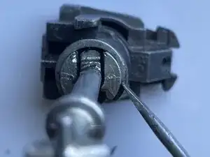
Locate the front view of the door lock—this is the side from which you will remove the internal parts.
-
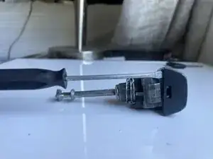
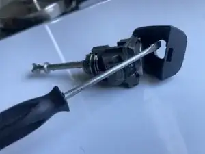
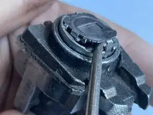
Use a pick tool to slide under the ends of the metal piece and apply moderate force to lift it free.
-
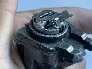
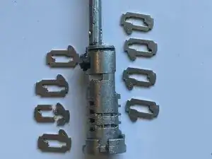
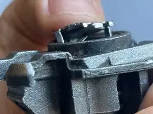
It should jumble up like this when you lift the Metal clamp off from the side.
-
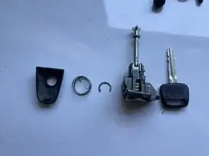
As the parts loosen, remove them one by one and organize them for reassembly. Caution: Small pieces may fall out—work over a tray or towel to prevent loss.
-
-
-
Remove The Cylinder By Key
-
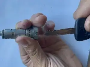
Important: Important: Do not remove the cylinder with your hands. , Doing so can cause the internal pins to fall out, making reassembly difficult and time-consuming. Always insert the key before removing the cylinder to keep the pins securely in place.
-
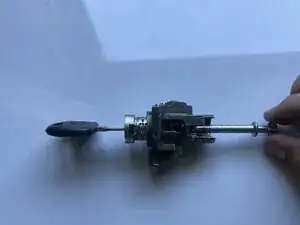
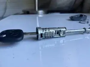
Insert the key fully into the door lock. Once it is all the way in, pull the key and cylinder assembly out from the metal housing.
-
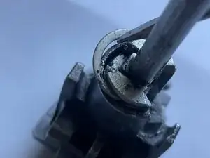
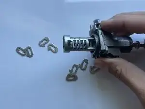
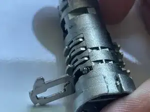
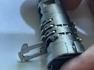
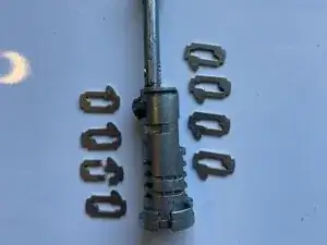
After removing the cylinder with the key inserted, you’ll notice several pins extending from the cylinder. These are the lock pins that need to be removed.In this case, only one pin is damaged and requires replacement.
-
-
-
Carefully Extract the Broken Pin(s)
-
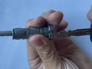
Use both of your fingers to cover the side pins
-
Remove the key while covering the side pins, this will avoid the pins from springing away from the cylinder. (This should remind you from the important side note that pins can easily fall out or jump out of the cylinder when moved.)
-
IMPORTANT: Begin removing the pins from the bottom left—this is the first pin position. Be extremely careful not to drop any of the small springs located in the pin chambers.
-
Release each pin one at a time, following the order shown in the reference image on the left. The pins on the top align with the springs, while the bottom pins face downward toward the key slot. Once you identify the damaged pin, carefully remove and discard it.
-
-
-
Remove the pins carefully and extract the broken pin.
-
Use both fingers to cover the side pins, then carefully remove the key while keeping the pins covered. This prevents the pins from springing out of the cylinder. (Remember, the pins can easily fall or jump out of the cylinder if the key is removed without support.)
-
IMPORTANT: Begin removing the pins from the bottom-left chamber—this is the first pin position. Be extremely careful not to drop any of the small springs located inside the pin slots. You may use pliers or a precision tool to carefully lift each pin out of the cylinder.
-
Side note: The broken pin may be difficult to remove and could require additional force to extract. Be sure to keep track of the order of each pin in case they are removed or mixed up during the process.
-
-
-
Assemble all components together, then properly put all three metal components onto the key hole.
-
Take the two metal components and position them on top of the spring, aligning both ends of the metal pieces with the holes where they’ll latch in place. This step can be tricky due to the tension of the spring. You might need a few attempts to make sure everything stays aligned.
-
Hold both metal parts in place with your finger, as shown in the left photo. On the right, you’ll see the peg — it needs to go into the socket hole.
-
Use a small screwdriver to help guide it in. Once all three metal components are in position and the pegs are seated properly, it should look like the final photo on the right.
-

To reassemble your device, follow these instructions in reverse order.