Introdução
Use this guide to track down every common cause of a Hotpoint dryer that refuses to run and learn how to fix each fault, including replacing the door switch that most often fails. Follow each check in order to avoid needless disassembly and keep yourself safe while working around live voltage and sharp edges.
-
-
Turn the timer clockwise and listen for a strong clicking sound from the mechanism.
-
Pull the knob straight off and examine the plastic insert for cracks or stripping.
-
Check the exposed metal shaft for rounding or breakage that prevents rotation.
-
-
-
Use a flat bladed screwdriver to pry the plastic button from the console without twisting the clips.
-
Look for cracks, deformation or missing plastic that could keep the plunger from reaching the switch.
-
Press directly on the exposed switch body to see whether the dryer starts with the button removed.
-
-
-
Open the door and tape the door switch closed so the machine thinks the door is shut.
-
Rotate the drum counter-clockwise while pressing the start button.
-
-
-
Slide the dryer forward, remove the single quarter-inch screw and drop the rear lower cover that guards the cord block.
-
Look for burnt, loose or broken wires on the terminal block and power cord ends.
-
-
-
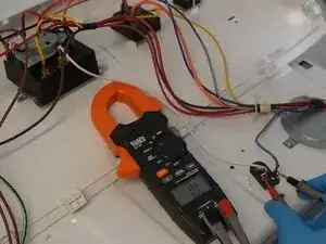
Set the multimeter to AC volts, keep the dryer plugged in and measure center to left then center to right posts; both should read about 120 V.
-
Measure across the two outer posts and confirm 208-240 V.
-
-
-
Unplug the dryer, set the meter to continuity and touch a lead to each terminal of the small fuse on the blower housing base.
-
-
-
Take out two quarter-inch screws on the plastic end caps and four more securing the steel rear console cover.
-
-
-
Remove the green ground screw so the console can pivot upward and clear the top.
-
Put the meter on continuity, back-probe the top red and bottom brown wires and press the start button.
-
-
-
With the schematic as reference, rotate the timer to a heat cycle and check continuity through the motor circuit terminals.
-
-
-
Remove two Phillips screws from the rear corners of the top panel and two more inside the door opening.
-
Slide a flat blade under the front seam to release the spring clips and raise the lid slightly.
-
-
-
Support the raised lid and unplug the small lamp harness at the left hinge area, pressing the locking tab while separating.
-
-
-
Extract one quarter-inch screw from each front side flange and prepare to lift the entire door panel.
-
Pull the panel forward and upward to clear the three bottom fingers that support it.
-
Slide the plastic guard aside, squeeze the latch and unplug the switch harness, then set the door panel aside.
-
-
-
Reach your right hand behind the blower housing, pull the idler arm to the right and hook its metal hub on the motor bracket tab.
-
Slip the drum belt off the motor pulley and idler wheel completely.
-
-
-
Grab the loose belt, raise the drum slightly and pull it straight forward, keeping it inside the stamped side channels.
-
Guide the rear bearing out of its socket while avoiding snags on the belt or cabinet edges.
-
-
-
Vacuum loose lint from the motor, blower housing and cabinet floor to restore airflow and prevent future fuse trips.
-
-
-
Pull one blue wire from the two-terminal thermostat on the blower outlet and read resistance across the exposed spades.
-
Measure the small orange terminals and expect roughly 9 kΩ at room temperature.
-
-
-
Remove one lead from the small fuse on the heater housing and verify continuity at 0 Ω.
-
Repeat the test on the adjacent high-limit thermostat; OL indicates the part is blown.
-
-
-
Keep the meter on continuity, pull the idler arm until you hear a click and watch for 0 Ω on the meter.
-
-
-
Press the hidden clip on the switch body, slide it toward the drum and withdraw the switch from the panel.
-
Using the schematic, verify continuity between the white and brown wires with the switch released for the light circuit.
-
Close the switch plunger and verify continuity now shifts to the brown and yellow wires that feed the motor circuit.
-
-
-
Slide the replacement switch into the front panel until the side clip locks behind the metal skin.
-
Reconnect the three-wire harness firmly, ensuring the plastic guard snaps back over the connector.
-
-
-
Pull the idler arm onto its motor mount tab to hold tension back while you work.
-
Seat the belt in the rear drum groove, lift the drum and slide the rear bearing into its socket at the back panel.
-
Loop the belt around the motor pulley, release the idler arm and verify the belt tracks in the center of both pulleys.
-
-
-
Rotate the drum by hand several turns and confirm the belt rides smoothly and no scraping sounds are present.
-
-
-
Hang the panel on the three lower chassis fingers and pivot it toward the cabinet until flush.
-
Reconnect the door switch harness if you left it detached and tuck the plastic guard back in place.
-
Install the two quarter-inch screws through the side flanges to secure the panel.
-
-
-
Swing the lid down, press along the front edge until both spring clips snap into the chassis.
-
Plug the dryer in and press start to confirm the repair restores full motor and heat function.
-
-
-
Drive the two long Phillips screws into the door opening to lock the top to the front bulkhead.
-
Insert the two matching screws at the rear corners of the lid.
-
Pivot the console down, align the six plastic fingers with their slots and tap forward to lock.
-
Reinstall the green ground screw and the four quarter-inch screws that hold the metal console cover.
-
Finish by replacing the two top console mounting screws.
-
-
-
Run the dryer through a full heat cycle and monitor for normal sound, drum rotation and temperature rise.
-
Your Hotpoint dryer should now start reliably and run through its cycles. Regularly clean lint from the cabinet and vents to prevent future fuse or thermostat failures, and remember that any future no-start condition can be re-checked quickly using the tests in this guide.