Introdução
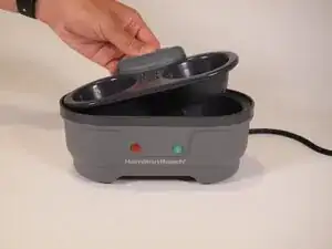
This guide shows how to disassemble a Hamilton Beach 25506 Egg Bite Maker.
Please make sure that your device is not connected to any outlet before you begin. Be careful with keeping track of screws.
Some users report that eggs are not being cooked. If this happens, make sure to put water between the egg cooker and the appliance. Then try the appliance again. If this problem persists, continue with disassembly.
The link below is also to a user guide to help users navigate this appliance:
USER GUIDE: https://useandcares.hamiltonbeach.com/fi...
Ferramentas
-
-
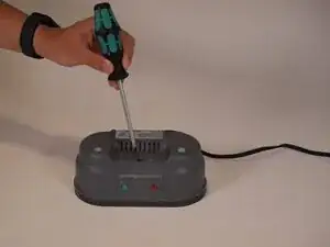
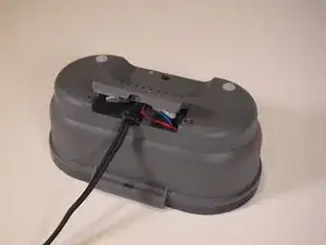
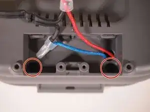
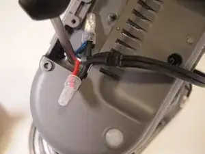
Flip the egg bite maker upside down.
-
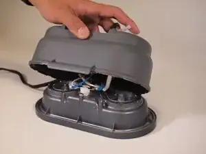
Remove the single 13mm screw using a Phillips #2 screwdriver.
-
-
-
Remove the two 12mm screws near the bottom two sides of the panel using a Phillips #2 screwdriver.
-
-
-
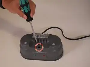
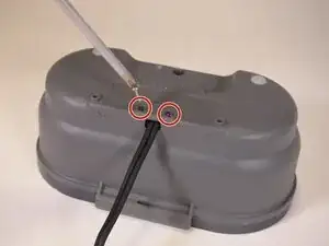
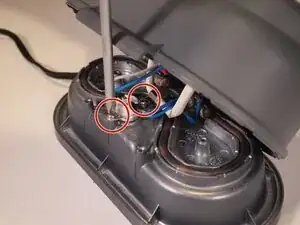
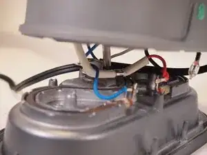
Remove the two 8 mm screws from the temperature limit controller using a Phillips #2 screwdriver.
-
-
-
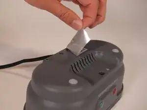
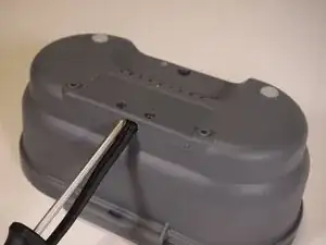
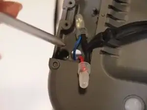
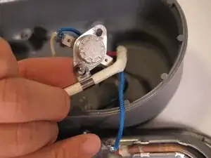
To access the second screw that holds the temperature limit controller in place, place the screwdriver through the panel on the plastic top.
-
After placing the screwdriver through the hole in the top, align the screwdriver with the second screw, and then remove it.
-
-
-
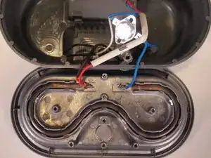
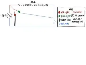
The following bullet points describe how the Hamilton Beach 25506 Egg Bites Maker functions:
-
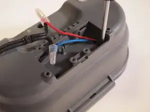
When connected to the outlet, the current flows through the red wire (hot) and will flow out of the blue wire (neutral).
-
The current goes through the red wire and then through the hot coil, the red light, and the green light. Both lights will shine when the device is plugged in and ready to be used.
-
The current continues through the hot coil and at the end of the hot coil, goes through the blue wire.
-
The blue wire carries current through the temperature limit controller and through the green light. When the temperature exceeds 115 degrees celsius, the temperature limit controller switches the green light off. This signals to users that the egg bites are ready.
-
After this, the temperature limit controller sends the current back to the outlet via the blue wire.
-
The schematic diagram attached to this step shows a diagram of how this circuit operates inside of the appliance.
-
To reassemble your device, follow these instructions in reverse order.