
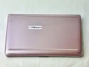
Introdução
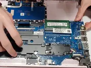
If your laptop does not turn on, fails to display properly, or completely freezes, and the battery, AC adapter, and RAM card has already been determined to work properly, then the issue is likely due to a failure on the motherboard, whether it be the CPU or GPU which are soldered on, RAM sockets, I/O controller, PCH, PMIC, or one of the many other systems on the motherboard.
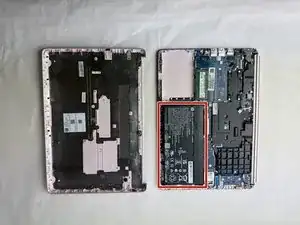
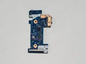
You will need to purchase a N12724-601 motherboard if you decide to replace it, and only used components are available for sale. The N12724-601 is the motherboard used in all HP 14-CF series laptops. Keep in mind that the motherboard is the most expensive component of the laptop to replace, and a used N12724-601 usually costs at least half the price of the whole laptop.
Before you begin this replacement guide, power off the laptop and remove any cable or device plugged into the ports, including the charging port.
-
-
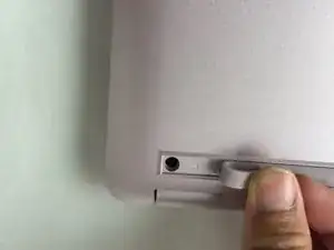
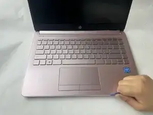
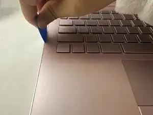
Use a spudger to pry under the end of the screw cover.
-
When the edge is lifted up, use your fingers to pull the rest of the strip off.
-
-
-
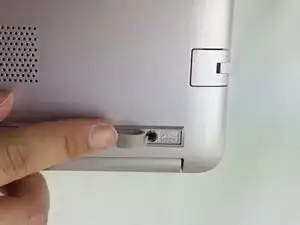
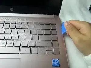
Use a pick or opening tool to pry along the edges of the back cover from the keyboard side of the laptop.
-
-
-
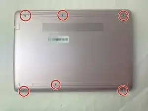
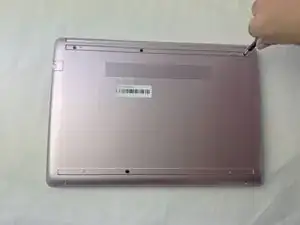
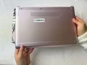
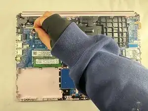
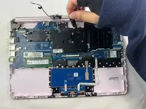
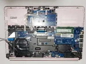
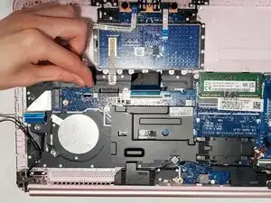
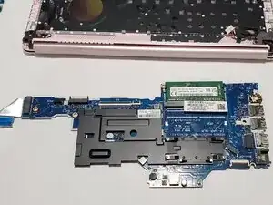
Place your opened laptop on a flat surface.
-
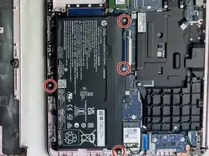
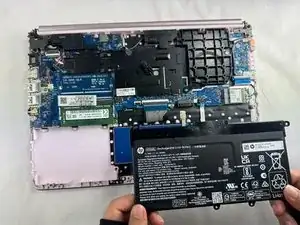
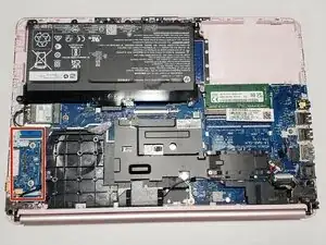
Use a Phillips #1 screwdriver to remove the four Phillips 3.0 mm screws securing the battery.
-
-
-
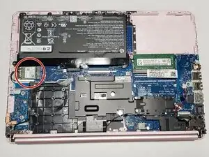
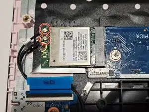
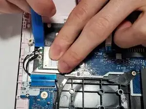
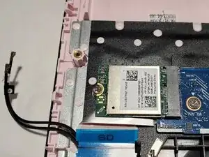
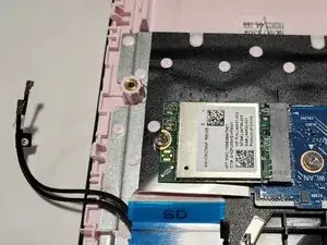
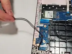
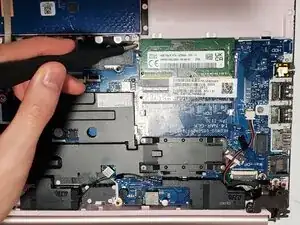
Use an opening tool to pry up and disconnect the two Wi-Fi card coaxial cable connectors.
-
The wire with the white tab attached should connect to spot number 1 on the Wi-Fi card. The wire with the black tab attached should connect to spot number 2.
-
-
-
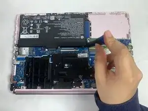
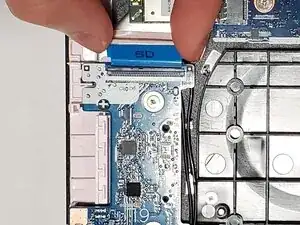
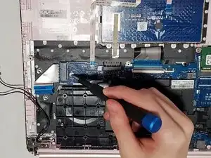
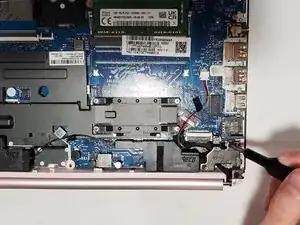
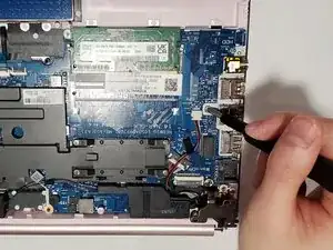
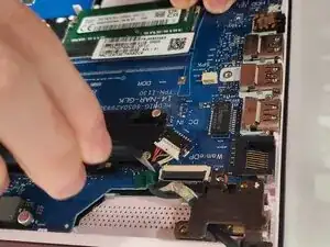
Use your fingers or tweezers to pull out the speaker cable from the slide connector socket on the motherboard.
-
If that doesn't work, use the point of a spudger to push on alternating sides of the connector to "walk" it out of its socket.
-
-
-
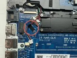
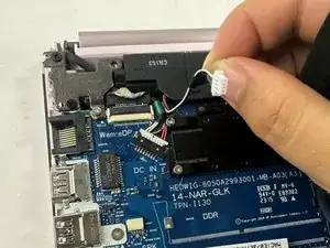
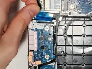
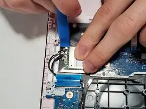
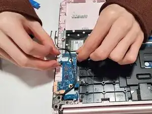
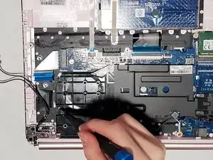
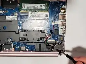
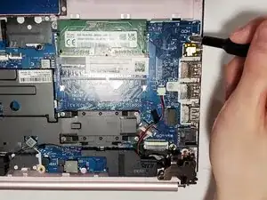
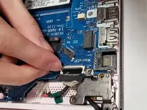
Flip up the black locking flap securing the ribbon cable to the daughterboard.
-
Disconnect the ribbon cable.
-
-
-
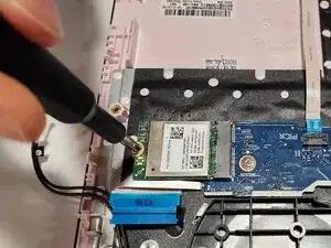
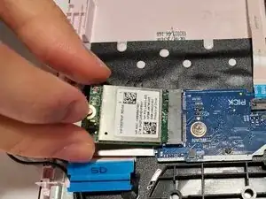
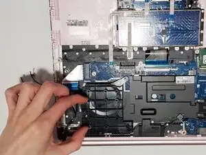
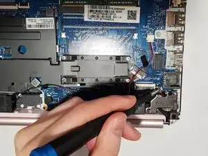
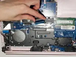
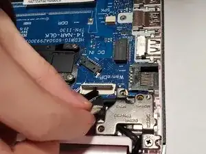
Remove the two 2 mm wide sliver screws securing the daughterboard with a Phillips #1 screwdriver.
-
-
-
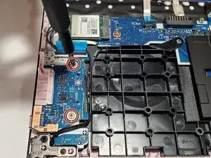
Remove the 3 mm-long screw near label named "BATJ" with a Phillips #1 screwdriver.
-
Remove the 3 mm-long screw near the label named "WLAN" with a Phillips #1 screwdriver.
-
-
-
Remove the remaining 3 mm-long screw on top of the large piece of black plastic labelled "A-1" with a Phillips #1 screwdriver.
-
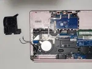
Remove the large piece of black plastic.
-
-
-
Remove the two 6.5 mm-long black screws with a Phillips #1 screwdriver.
-
Remove the one 3 mm-long screw on the metal hinge with a Phillips #1 screwdriver.
-
-
-
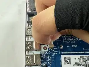
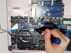
Remove the wide 2 mm-long screw next to the RAM module with a Phillips #1 screwdriver.
-
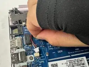
Remove the 3 mm-long screw next to the label named "SPK" with a Phillips #1 screwdriver.
-
Remove the 3 mm-long screw next to the label named "HHD" with a Phillips #1 screwdriver.
-
-
-
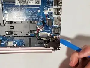
Flip up the two black locking flaps near the touchpad, one wide and one thin.
-
Disconnect the two ribbon cables with blue ends.
-
To reassemble your device, follow the above steps in reverse order.
Take your e-waste to an R2 or e-Stewards certified recycler.
Repair didn’t go as planned? Try some basic troubleshooting or ask our Answers community for help.