Introdução

  1. YBjDeq1ifowKDuH2
    YBjDeq1ifowKDuH2
    hqDTKYRPsASVBNJB
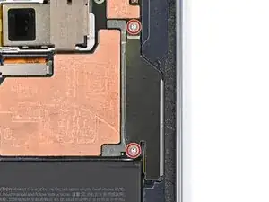
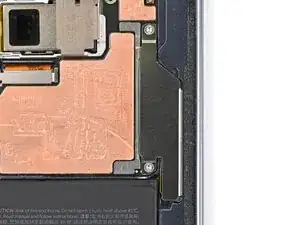
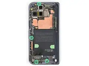
    • Use a Torx Plus 3IP driver to remove the two 2.8 mm‑long screws securing the interconnect cable bracket.

    • The bracket will sit upright when its screws are removed.

  2. 1NLSqcsTTg6J2KKg
    1NLSqcsTTg6J2KKg
    4pK12lEZ5uRDxwQI
    • Lift the interconnect cable bracket straight up out of its slot in the frame and remove it.

  3. HHAxZpwy3JZIREEV
    HHAxZpwy3JZIREEV
    AVQCJAuiPkBVJqIj
    XlDcWIfRSHUKDnsb
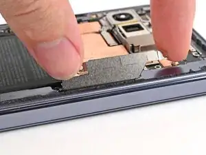
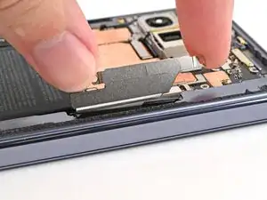
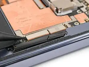
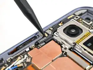
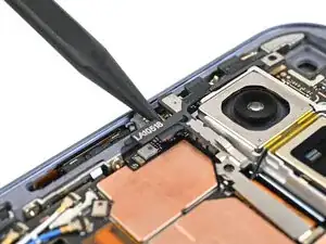
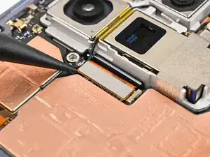
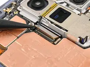
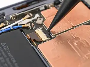
    • Use the point of a spudger to pry up and disconnect the interconnect cable press connectors.

  4. sBA2bHBrkrWAlt1h
    sBA2bHBrkrWAlt1h
    v1yc5xOtA2yTyQ16
    • Use a Torx Plus 3IP driver to remove the 2.8 mm‑long screw securing the inner display connector bracket.

  5. bRVtOoLhk5SVWEcN
    bRVtOoLhk5SVWEcN
    pEbJKIpfo2Bk1poC
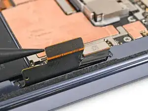
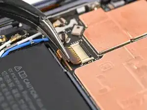
    • Use the point of a spudger to pry up the inner screen connector bracket and release its plastic clip from the left edge of the frame.

  6. kVYGr3GvQcOhgJ3F
    kVYGr3GvQcOhgJ3F
    bDLpDpj4BKldQRrQ
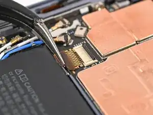
    • Pull the inner display connector bracket towards the left edge of the phone to release its metal clip.

  7. BRruPXOXxdyZ1n2H
    BRruPXOXxdyZ1n2H
    op21TxE4mbSYGvSa
    • Use the point of a spudger to pry up and disconnect the inner screen press connector.

  8. IGrpnmjRPURZjNLJ
    IGrpnmjRPURZjNLJ
    T1YdvkoboTBP1Yye
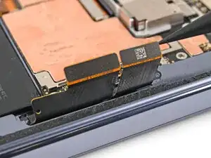
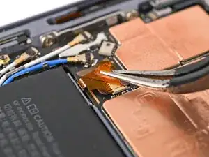
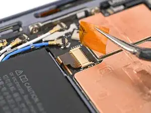
    • Use tweezers, or your fingers, to peel off the yellow tape on the side button cable ZIF connector.

    • Set the tape aside. You'll need it during reassembly.

  9. YZkQHyGNRWhMsygq
    YZkQHyGNRWhMsygq
    ZBDceInMHpRG1rme
    • Use the point of a spudger, or your fingernail, to lift the locking tab on the side button cable ZIF connector.

  10. PBqKb3ALo4uCS2RW
    PBqKb3ALo4uCS2RW
    2LThNLJgPRZA1Mf3
    • Use angled tweezers to pull the side button cable straight out of its slot.

    • Take care not to puncture the battery—it can leak dangerous chemicals and/or catch fire.

  11. 2XMkTTZG6s2SdiEZ
    2XMkTTZG6s2SdiEZ
    t4NFmpBxLMjnw4xo
    • Use a Torx Plus 3IP driver to remove the four 2.8 mm‑long screws securing the logic board.

  12. HkDatMXL4bwBlHJ5
    HkDatMXL4bwBlHJ5
    rP3BqDYWI43sLpWB
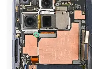
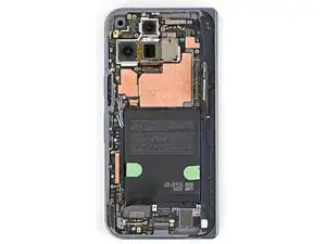
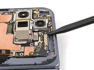
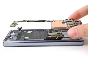
    • Insert a spudger under the top edge of the logic board, next to the 5G mmWave antenna cutout.

    • Pry up the logic board enough so you can grip the top edge with your fingers.

    • You might feel some resistance since the logic board is bonded to the frame by thermal paste.

  13. CGXOFsYW5tJfIF1b
    CGXOFsYW5tJfIF1b
    awSXysbWoiPISEUV
    xQgiRsUNXrN1xhjg
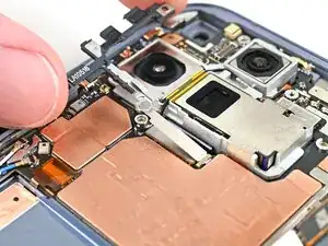
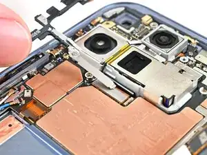
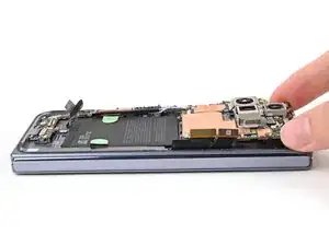
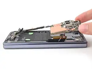
    • Lift the top of the logic board slowly until the clips at the bottom edge of the logic board release.

    • Slide the logic board out of the USB-C port cutout and remove it.

  14. AEd5V6O3jVC1BWfY
    AEd5V6O3jVC1BWfY
    RraU23oKEAKoHOmC
    JBCNgTYtlD2531BY
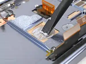
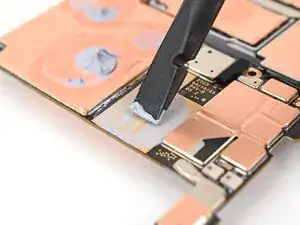
    • Use the flat end of a spudger to scrape off all of the thermal paste from the frame.

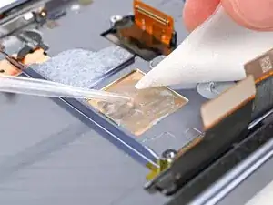
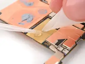
    • Apply isopropyl alcohol (>90%) and use a coffee filter or microfiber cloth to clean any thermal paste residue.

  15. D2eWEr6sivB6jsYo
    D2eWEr6sivB6jsYo
    5cwNQdWCPHLaGVRB
    gpRfi4pyWlyFa1TG
    • Repeat the previous step to remove thermal paste on the back of the logic board.

Conclusão

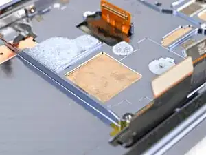
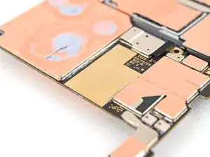
To reassemble your device, follow these instructions in reverse order.

Alex Diaz-Kokaisl

Membro desde: 16/01/22

227430 Reputação

0 comentários