Introdução

  1. bAlWEMLYNKiY5e23
    bAlWEMLYNKiY5e23
    Nw5TCgDYrVI3XxLv
    NoXkHZ1LrxhPGHpY
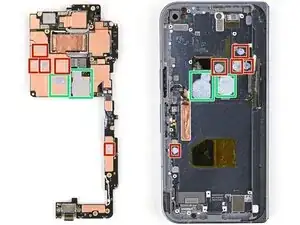
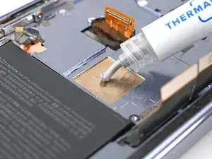
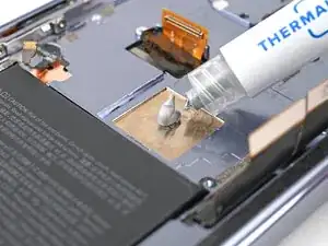
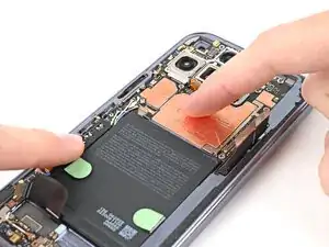
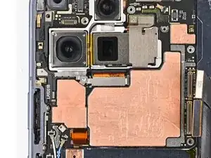
    • Apply thermal paste (seven total) to the motherboard in the same locations as the old thermal paste:

    • Five small beads of thermal paste

    • Two larger, "pea-sized" beads of thermal paste

  2. PLhtU1rpl1PcHUhk
    PLhtU1rpl1PcHUhk
    XMwaYaQKeRiPnJYY
    26bC3Bi1YoyiIbPb
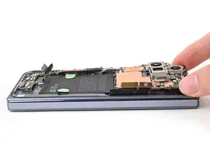
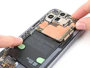
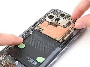
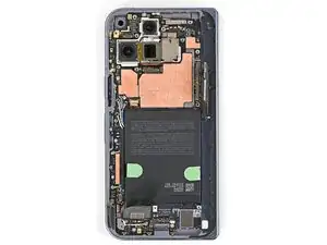
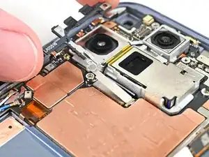
    • Place the logic board back into its cutout in the frame, making sure no cables get trapped underneath it.

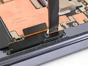
    • While pushing the logic board toward the bottom edge of the phone, press the logic board into its alignment pegs.

    • The bottom of the logic board should sit even with the frame.

  3. b1ZPrheTtP4LQQp2
    b1ZPrheTtP4LQQp2
    LcPK3pHDJ1RbGHbi
    pWFlOts2RLhlgnBx
    • This step can be tricky. Work slowly and follow the directions closely to make sure you install the logic board properly.

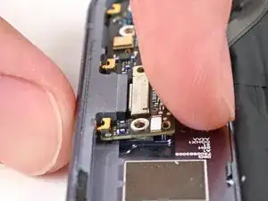
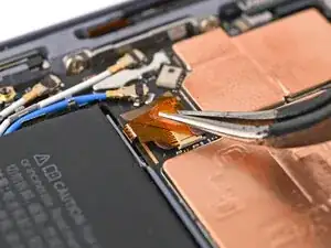
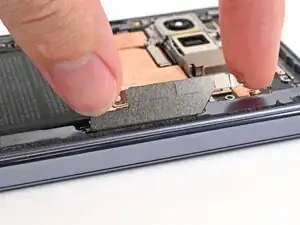
    • While using one hand to press down the thin vertical section of the logic board, use your other hand to press on the top section of the logic board against the left edge of the frame and engage its grounding clip.

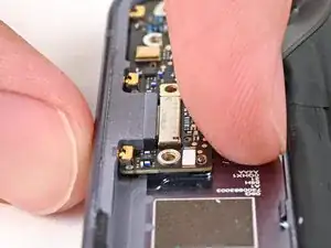
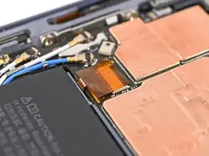
    • Press the logic board straight down to slot it into its alignment peg.

    • The logic board should sit flat in the frame and shouldn't be able to spring up and down. If it's not seated properly, lift the logic board out of the frame and try again.

  4. WraYELO5jsGLVFFv
    WraYELO5jsGLVFFv
    AZE1fkxcSRiGu1uX
    • Use a Torx Plus 3IP driver to install the four 2.8 mm‑long screws securing the logic board.

  5. pjQDhjV3MvTa3VrM
    pjQDhjV3MvTa3VrM
    xQIWy2TiLEu5UFOl
    • Use angled tweezers to slide the side button cable straight into its slot.

    • Take care not to puncture the battery—it can leak dangerous chemicals and/or catch fire.

  6. rIQ2lLgwGBYgYZPg
    rIQ2lLgwGBYgYZPg
    3RAIpoTjTYvXcXZM
    • Flip the locking tab down and lightly press on it until it clicks into place.

  7. SSUtPha4BJO6wJBW
    SSUtPha4BJO6wJBW
    UfYTEjEqUCSixXMP
    DT4xAfuYLlwckbAS
    • Place the yellow tape over the ZIF connector and its cable.

  8. YIKnABIgrBjF5Qti
    • Reconnect the inner screen press connector.

  9. HtBH5kmwVADZrV3r
    HtBH5kmwVADZrV3r
    KIE15sgkVC1XkDc4
    • Slide the inner display connector bracket's clip into its slot on the logic board.

  10. 63emUjESvXScu3VD
    63emUjESvXScu3VD
    NDo16RF3E2XxZKSZ
    MI4flTK1afhLdf3N
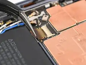
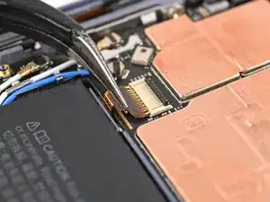
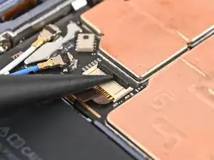
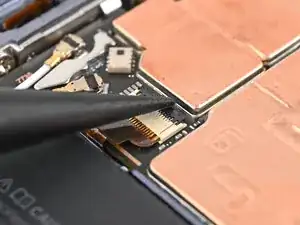
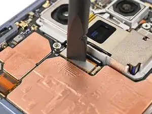
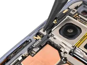
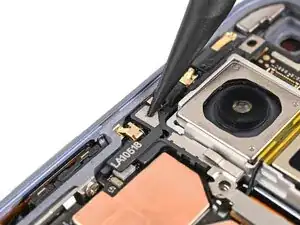
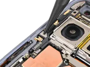
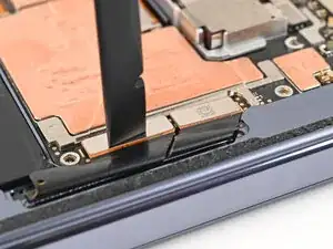
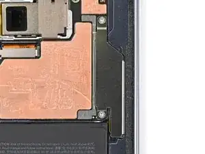
    • Use the point of a spudger to press down the bracket and slide its plastic clip into the left edge of the frame.

  11. e4C5CsXWE6ojiHkN
    e4C5CsXWE6ojiHkN
    bJpqC4uGtAAfeZIU
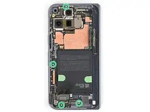
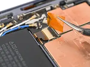
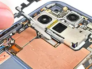
    • Use a Torx Plus 3IP driver to install the 2.8 mm‑long screw securing the inner display connector bracket.

  12. 1OCMHZSWJMugPuIB
    1OCMHZSWJMugPuIB
    ycR4iN4LFGy2rxu4
    • Reconnect the two interconnect cable press connectors.

  13. jZOXmDRWGifP2wJa
    jZOXmDRWGifP2wJa
    OdWGZhXQBikIYEZ1
    • Slide the interconnect cable bracket straight into its slot in the frame.

  14. gmJhQesqYOSIK4DO
    gmJhQesqYOSIK4DO
    drB2BE4BRAuoMiqv
    ZbuKFpxpHcc1JseW
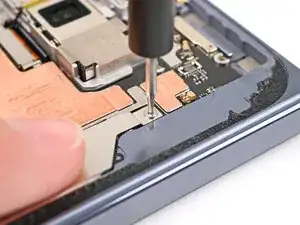
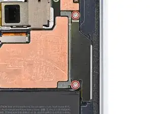
    • While pressing the bracket to the frame, use a Torx Plus 3IP driver to install the two 2.8 mm‑long screws securing the interconnect cable bracket.

Conclusão

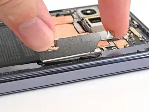
To reassemble your device, follow these instructions in reverse order.

Alex Diaz-Kokaisl

Membro desde: 16/01/22

227430 Reputação

0 comentários