Introdução
This repair guide was authored by the iFixit staff and hasn’t been endorsed by Google. Learn more about our repair guides here.
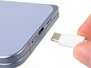
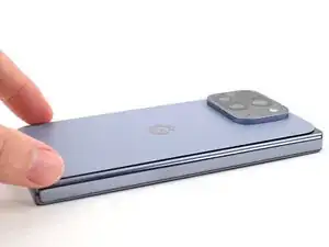
Use this guide to replace the inner screen assembly in your Google Pixel 10 Pro Fold.
The replacement inner screen assembly comes with the inner screen pre-installed into the frame. Replacing the inner screen requires transferring all of the internals to the new frame.
The inner screen assembly doesn't come with batteries. Do not transfer your old batteries; you'll need to source your own.
Some photos in this guide may contain slight visual discrepancies, but they won't affect the procedure.
Ferramentas
-
-
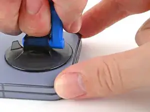
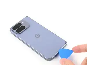
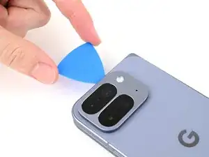
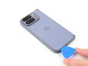
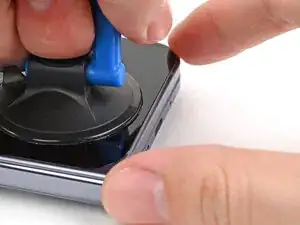
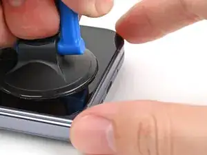
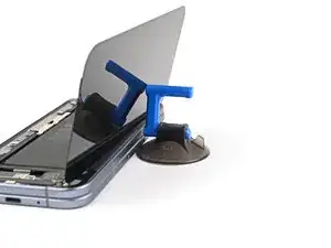
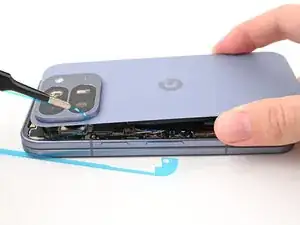
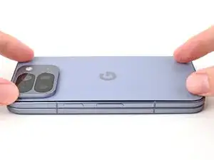
Apply a suction cup to the back cover, as close to the center of the bottom edge as possible.
-
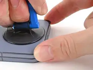
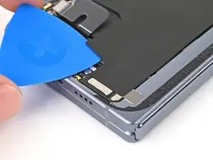
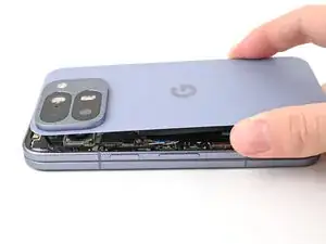
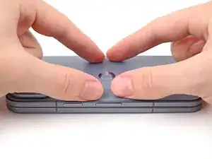
While securing the phone with one hand, pull up on the suction cup with strong, steady force to create a gap between the back cover and the frame.
-
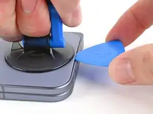
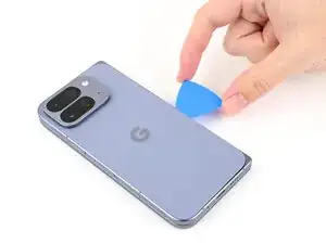
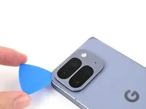
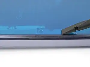
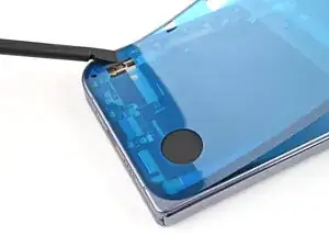
Insert an opening pick into the gap.
-
-
-
Remove the suction handle from the back cover.
-
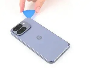
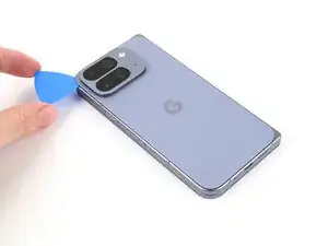
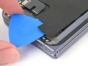
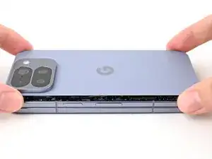
Slide the opening pick around the bottom right corner and up the right edge of the back cover to separate the adhesive.
-
-
-
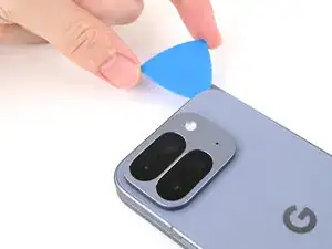
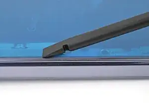
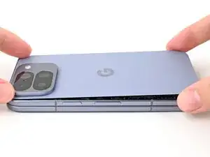
Continue sliding the pick around the top right corner and across the top edge of the back cover.
-
-
-
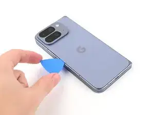
Slide your pick down the left edge and around the bottom left corner to separate the remaining adhesive.
-
-
-
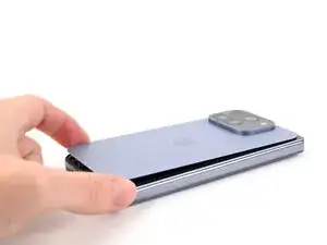
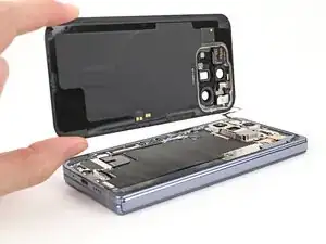
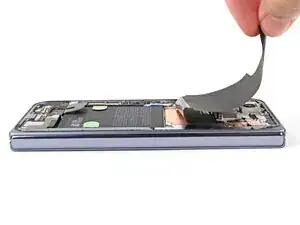
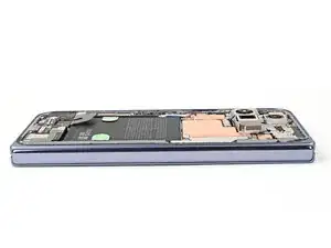
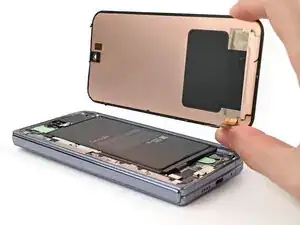
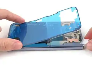
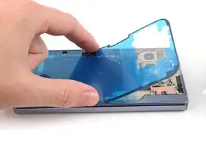
Lift the right edge of the back cover and swing it over the left edge of the phone.
-
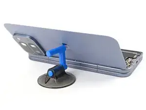
Prop up the back cover with your suction handle or a clean, sturdy object, making sure that the cable isn't strained.
-
-
-
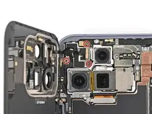
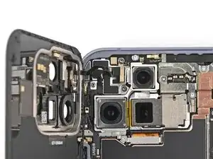
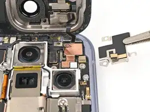
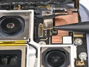
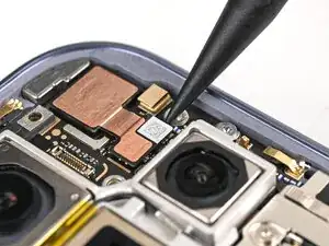
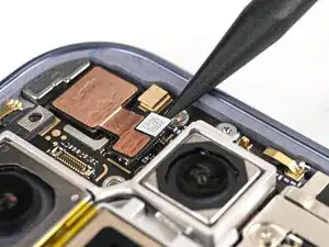
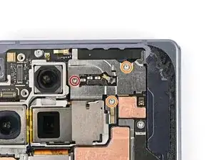
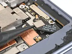
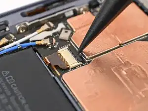
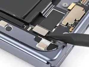
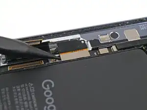
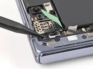
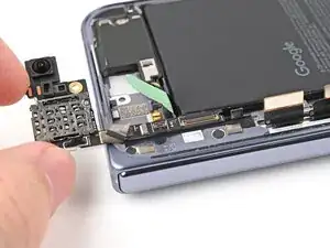
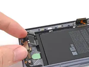
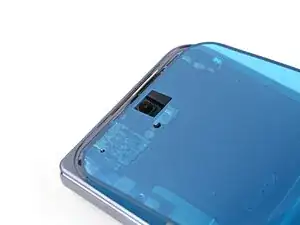
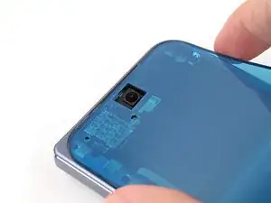
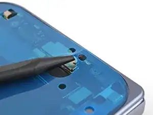
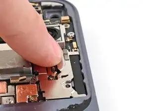
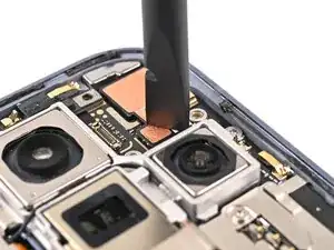
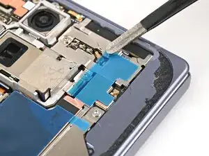
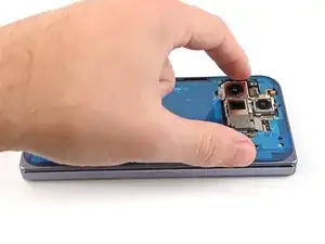
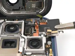
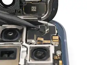
Use the point of a spudger to pry up and disconnect the inner front camera press connector.
-
-
-
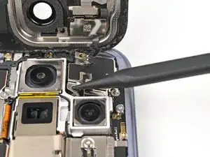
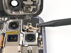
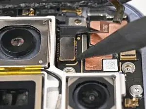
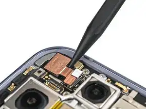
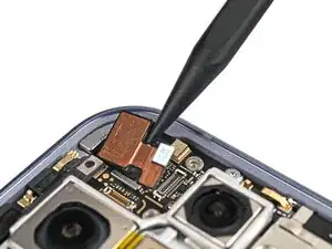
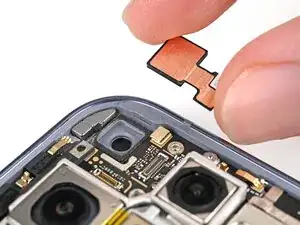
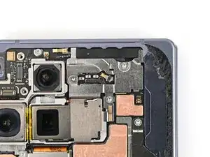
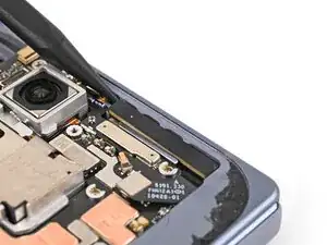
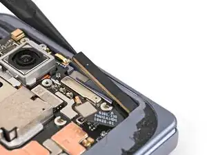
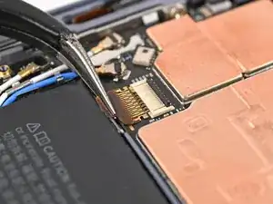
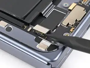
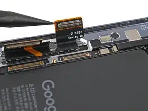
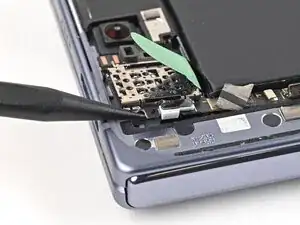
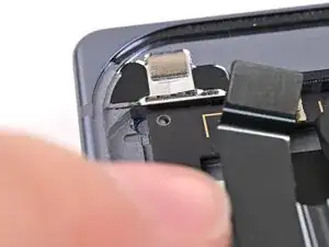
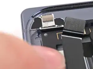
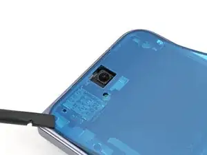
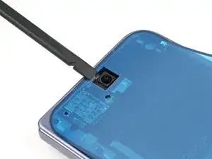
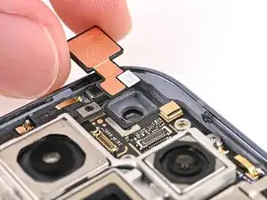
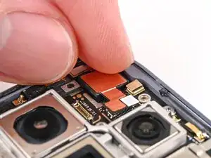
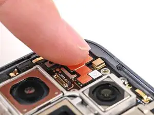
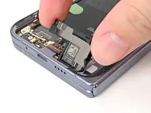
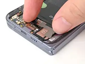
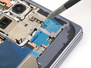
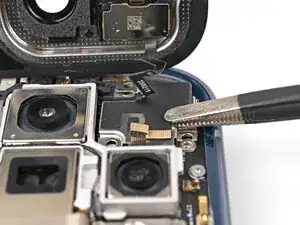
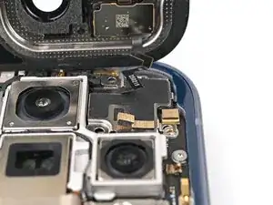
Insert the point of a spudger under the inner front camera cable and pry up to separate the adhesive securing the camera.
-
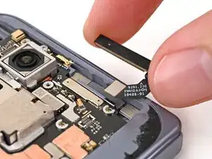
Remove the inner front camera.
-
-
-
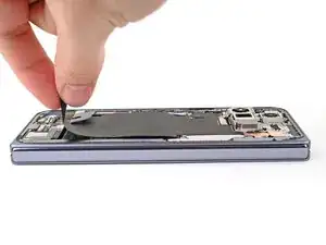
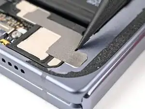
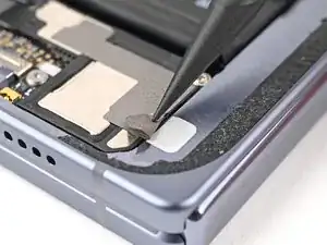
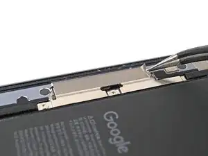
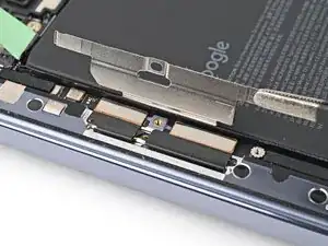
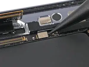
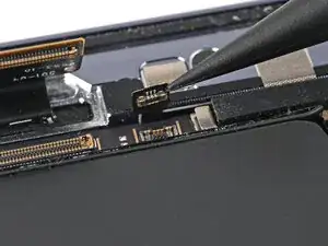
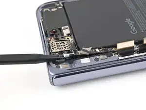
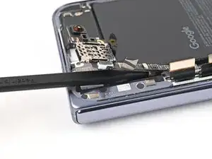
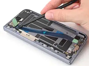
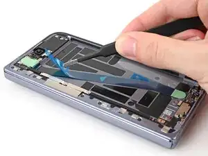
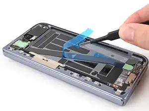
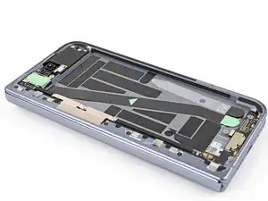
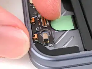
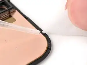
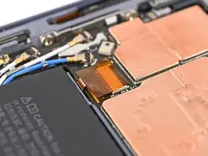
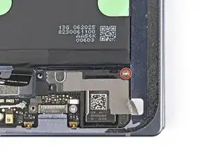
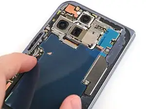
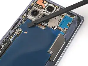
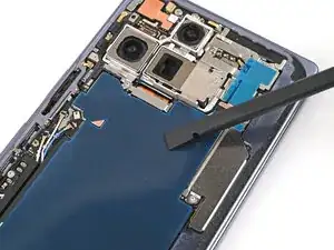
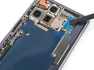
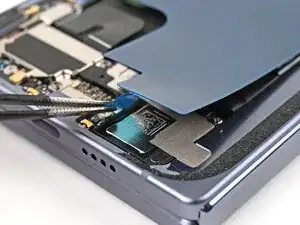
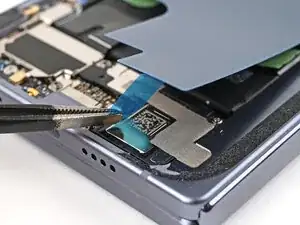
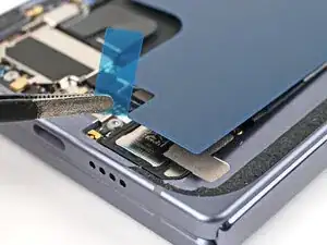
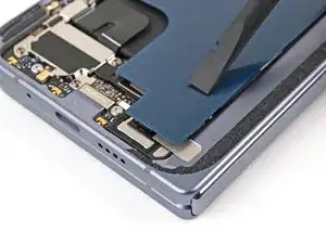
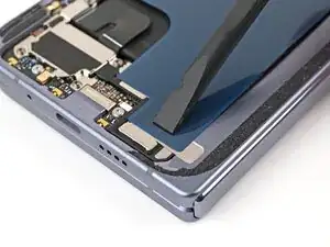
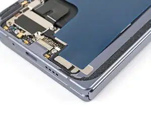
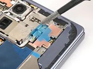
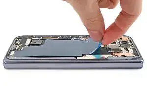
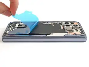
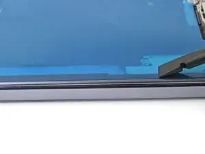
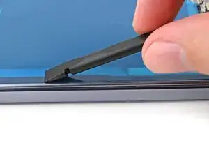
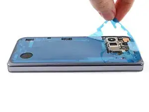
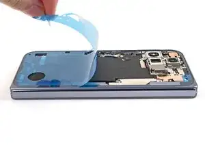
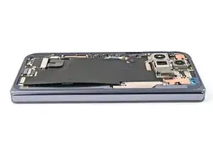
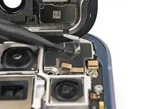
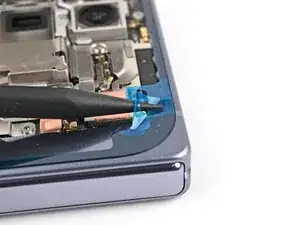
Slide an opening pick between the graphite sheet and the bottom speaker to separate the adhesive.
-
-
-
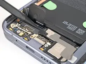
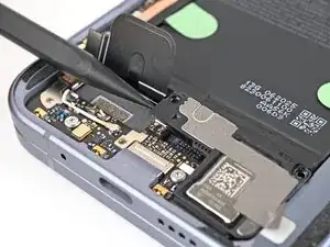
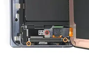
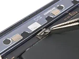
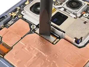
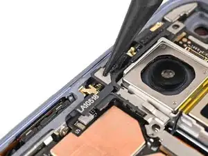
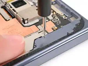
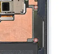
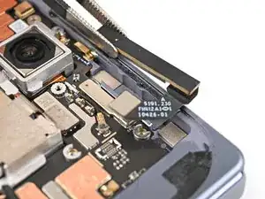
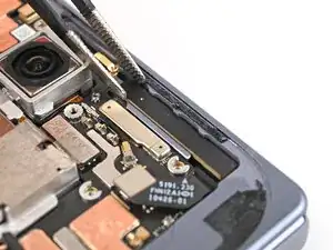
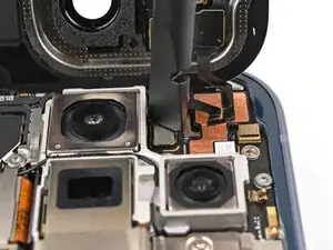
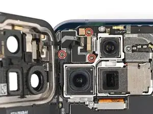
Use a Torx Plus 3IP driver to remove the three screws securing the antenna bracket:
-
One 1.9 mm‑long screw
-
Two 2.8 mm‑long screws
-
-
-
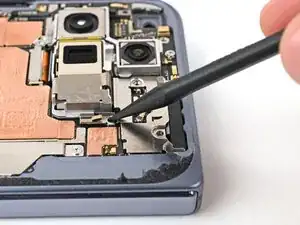
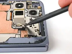
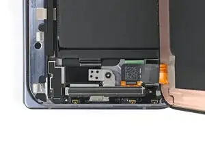
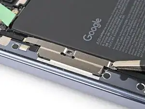
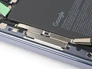
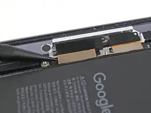
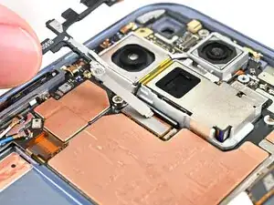
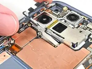
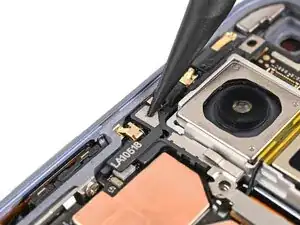
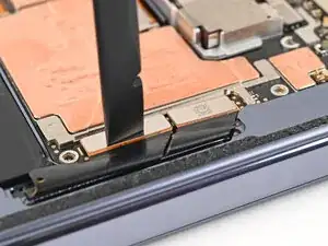
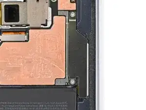
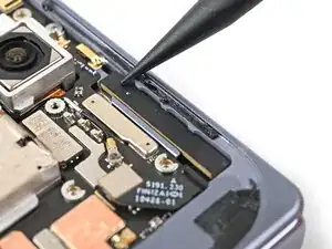
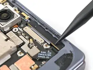
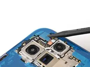
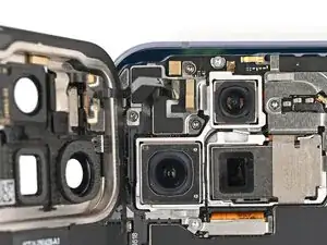
Use the point of a spudger to pry up the antenna bracket and release its two clips from the top and right edges of the frame.
-
-
-
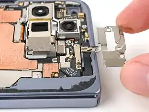
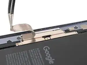
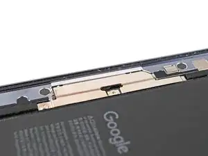
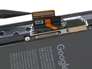
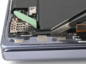
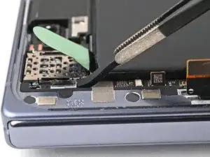
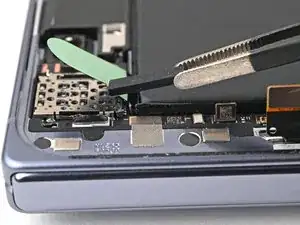
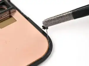
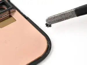
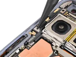
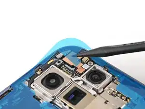
Insert the point of a spudger under the left edge of the 5G mmWave antenna.
-
Pry up the antenna to separate its adhesive and remove it.
-
-
-
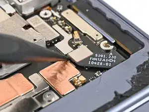
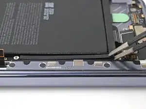
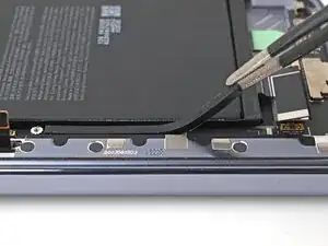
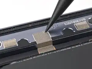
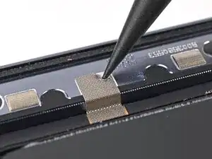
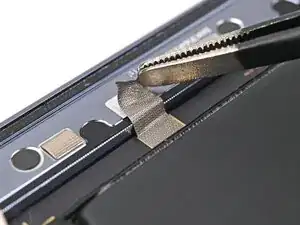
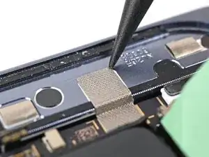
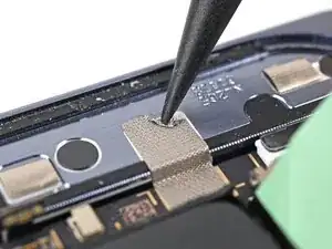
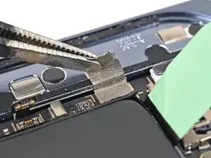
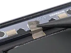
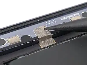
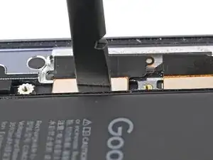
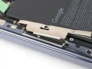
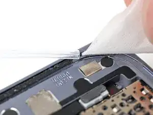
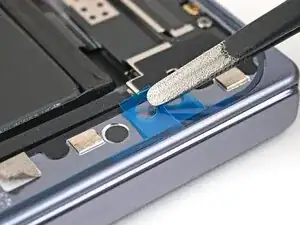
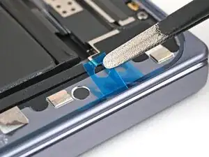
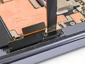
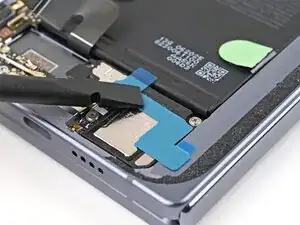
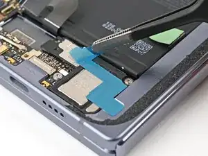
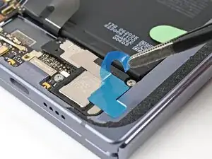
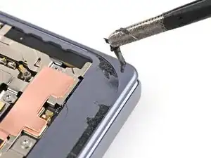
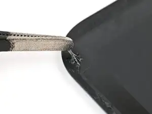
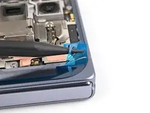
Use the point of a spudger to peel the section of conductive fabric connecting the loudspeaker to the frame.
-
-
-
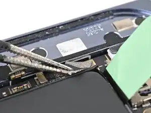
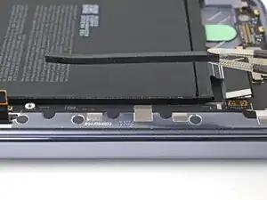
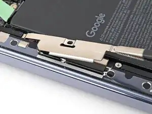
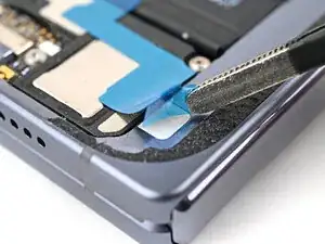
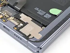
Use the point of a spudger to pry up the left edge of the loudspeaker to separate the adhesive securing it to the frame.
-
-
-
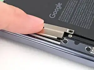
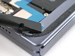
Use your fingers to lift the top edge of the loudspeaker and pull it out of its recess in the frame.
-
Remove the loudspeaker.
-
-
-
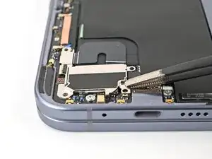
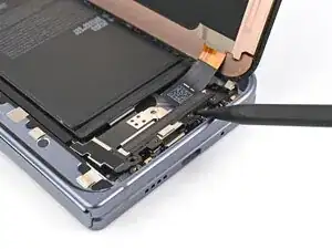
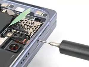
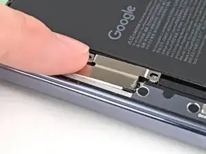
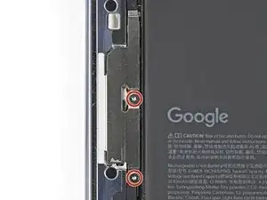
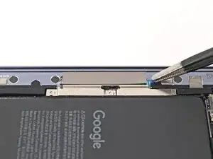
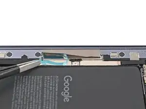
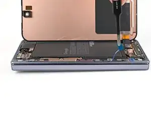
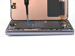
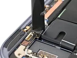
Use a Torx Plus 3IP driver to remove the two 2.8 mm‑long screws securing the interconnect cable bracket.
-
-
-
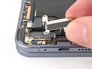
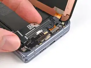
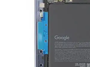
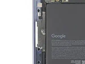
Lift the interconnect cable bracket straight up out of its slot in the frame and remove it.
-
-
-
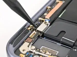
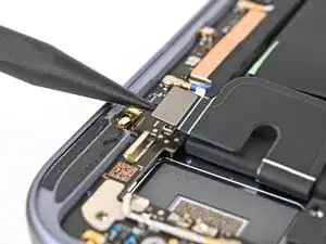
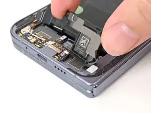
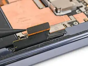
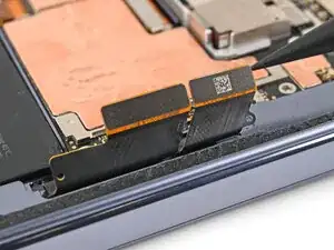
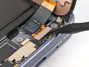
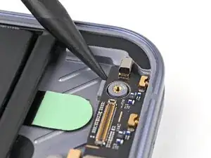
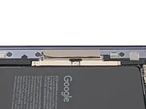
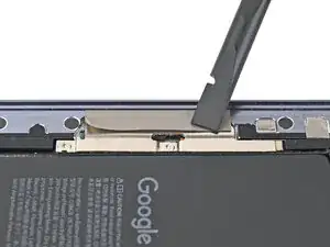
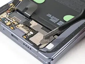
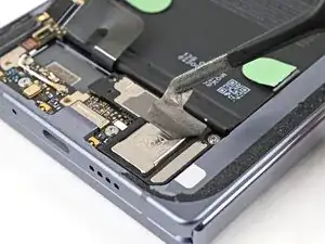
Use the point of a spudger to pry up and disconnect the interconnect cable press connectors.
-
-
-
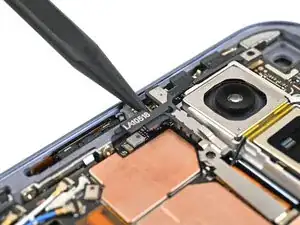
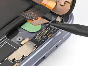
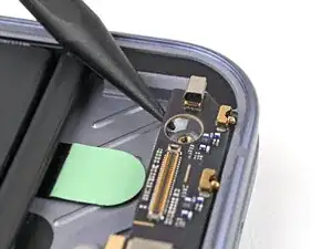
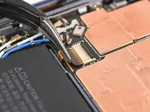
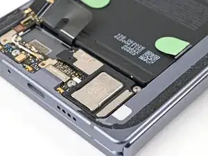
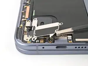
Use a Torx Plus 3IP driver to remove the 2.8 mm‑long screw securing the inner display connector bracket.
-
-
-
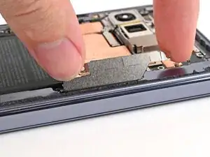
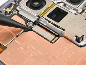
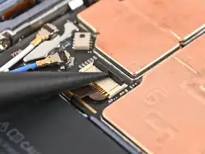
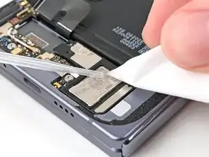
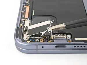
Use the point of a spudger to pry up the inner screen connector bracket and release its plastic clip from the left edge of the frame.
-
-
-
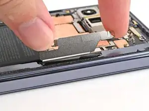
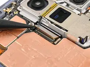
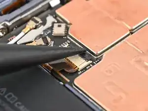
Pull the inner display connector bracket towards the left edge of the phone to release its metal clip.
-
-
-
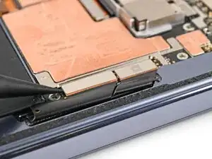
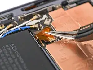
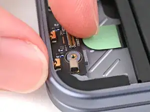
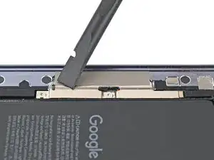
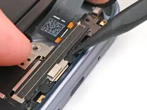
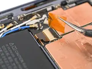
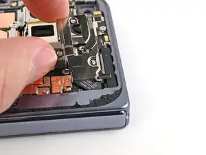
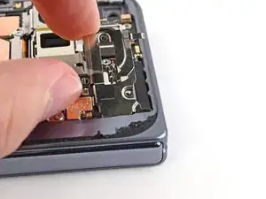
Use tweezers, or your fingers, to peel off the yellow tape on the side button cable ZIF connector.
-
-
-
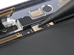
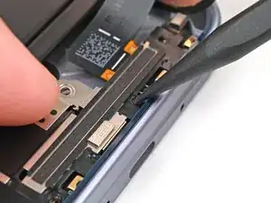
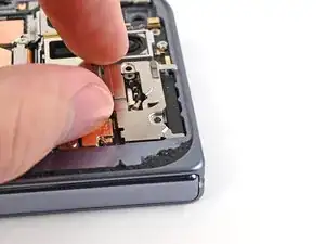
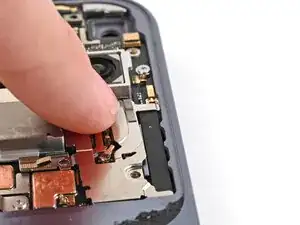
Use the point of a spudger, or your fingernail, to lift the locking tab on the side button cable ZIF connector.
-
-
-
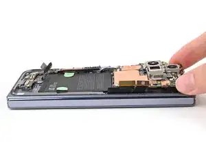
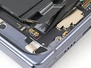
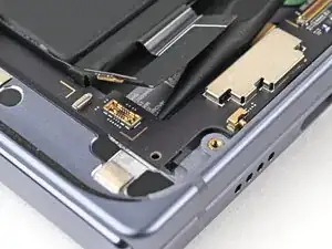
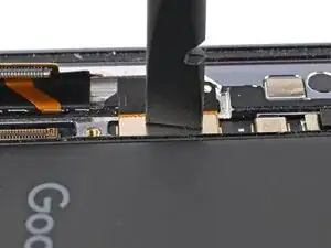
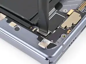
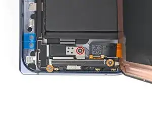
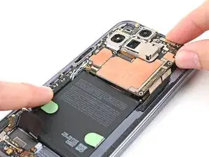
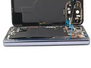
Insert a spudger under the top edge of the logic board, next to the 5G mmWave antenna cutout.
-
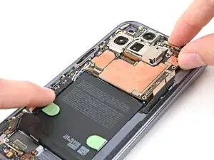
Pry up the logic board enough so you can grip the top edge with your fingers.
-
-
-
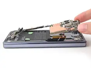
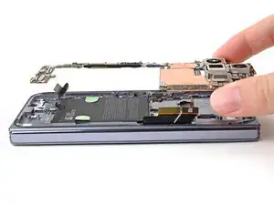
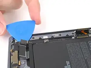
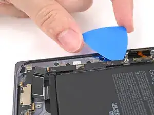
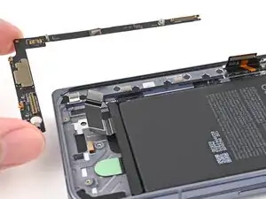
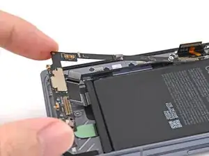
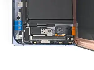
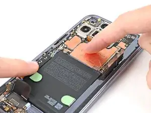
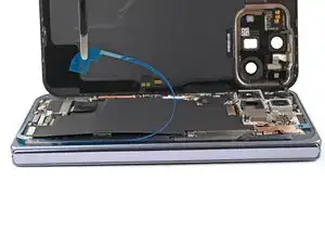
Lift the top of the logic board slowly until the clips at the bottom edge of the logic board release.
-
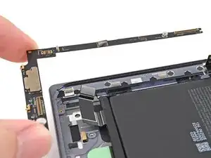
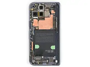
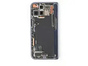
Slide the logic board out of the USB-C port cutout and remove it.
-
-
-
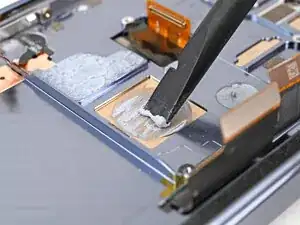
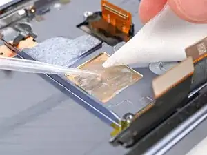
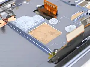
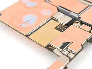
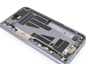
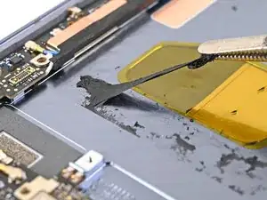
Use the flat end of a spudger to scrape off all of the thermal paste from the frame.
-
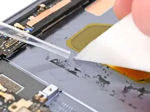
Apply isopropyl alcohol (>90%) and use a coffee filter or microfiber cloth to clean any thermal paste residue.
-
-
-
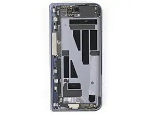
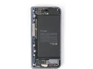
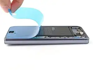
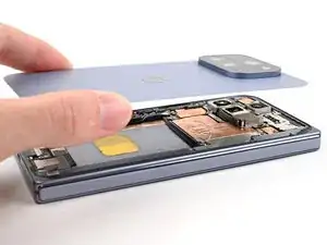
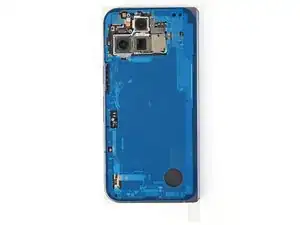
Place the back cover on the frame to protect the base battery while working on the flipside of the phone.
-
-
-
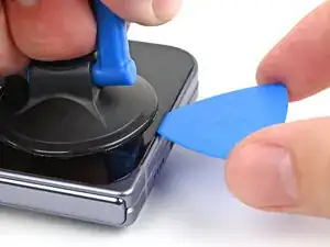
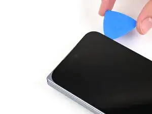
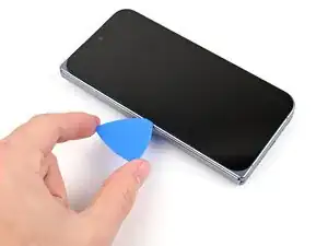
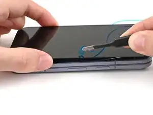
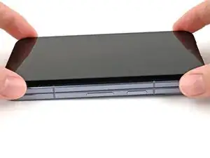
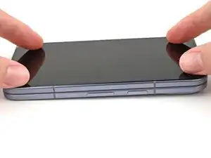
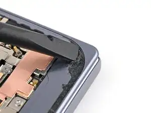
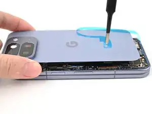
Apply a suction cup to the screen, as close to the center of the bottom edge as possible.
-
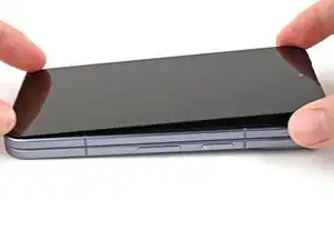
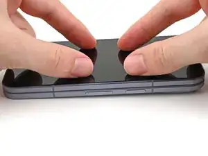
Pull up on the suction cup with strong, steady force to create a gap between the screen and the frame.
-
Insert an opening pick into the gap.
-
-
-
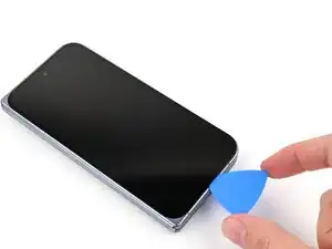
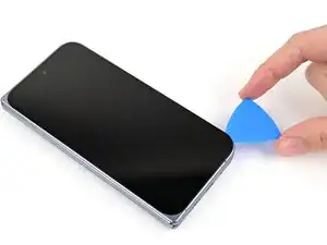
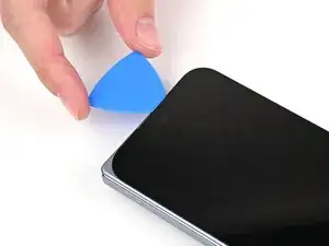
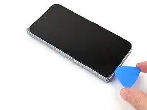
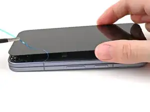
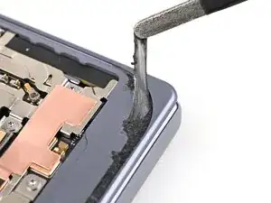
Slide the opening pick around the bottom right corner and up the right edge of the screen to separate the adhesive.
-
-
-
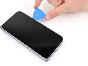
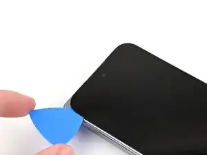
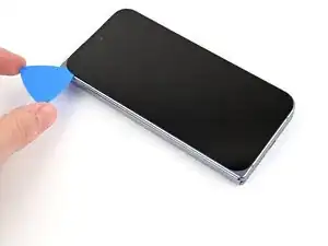
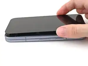
Slide your pick down the left edge and around the bottom left corner to separate the remaining adhesive.
-
-
-
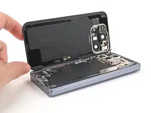
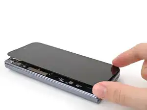
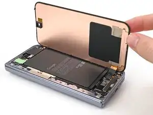
Lift the left edge of the screen and swing it over the right edge of the phone, like opening a book.
-
Prop up the screen with your suction handle or a clean, sturdy object.
-
-
-
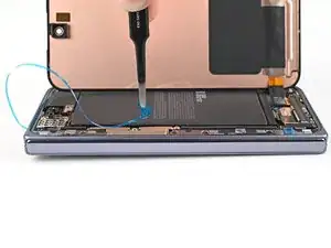
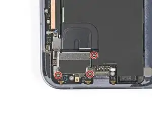
Use a Torx Plus 3IP driver to remove the three screws securing the display cable bracket:
-
One 1.8 mm‑long screw
-
Two 2.5 mm‑long screws
-
-
-
Use a Torx Plus 3IP driver to remove the two 2.8 mm‑long screws securing the interconnect cable bracket.
-
-
-
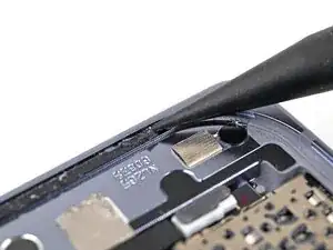
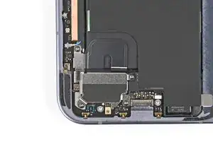
Use the point of a spudger to pry up and disconnect the interconnect cable press connector from the lower board.
-
-
-
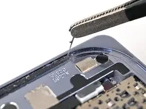
Use the point of a spudger to peel off the lower board's conductive fabric enough to grip it with tweezers.
-
-
-
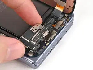
Use the point of a spudger to pry up the bottom right corner of the lower board until it's slightly above the edge of the frame.
-
-
-
Use the point of a spudger to pry up the bottom left corner of the lower board and lift it out of its alignment peg.
-
-
-
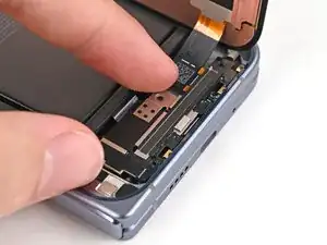
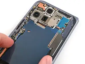
Slide an opening pick down the long section of the lower board to separate the adhesive securing it to the frame.
-
Remove the lower board.
-
-
-
Use the point of a spudger to pry up and disconnect the interconnect cable press connector from the upper board.
-
-
-
Use the point of a spudger to pry up and disconnect the antenna press connector from the upper board.
-
-
-
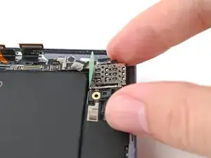
Use the point of a spudger to peel off the upper board's conductive fabric enough to grip it with tweezers.
-
-
-
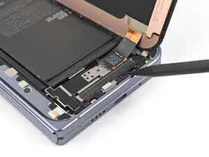
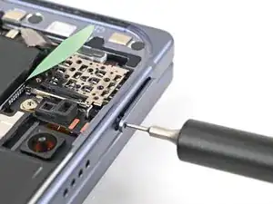
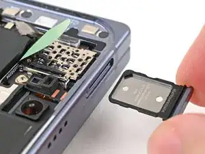
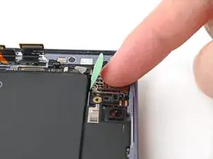
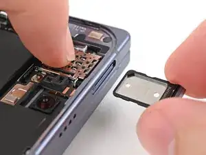
Insert a SIM eject tool, bit, or straightened paper clip into the SIM card tray hole and press firmly to eject it.
-
Remove the SIM card tray.
-
-
-
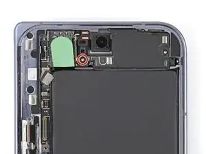
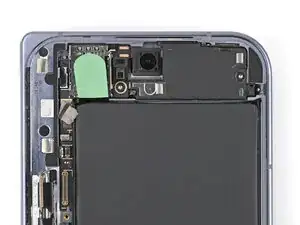
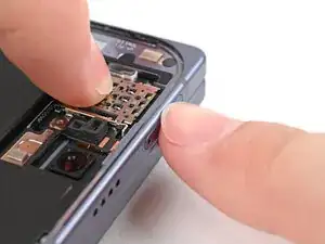
Use the point of a spudger to pry up the upper board and release its plastic clip from the left edge of the frame.
-
-
-
Slide the spudger under the length of the upper board to separate the adhesive securing it to the frame.
-
Remove the upper board.
-
-
-
Congratulations on completing disassembly! The remaining steps will show you how to reassemble your device.
-
-
-
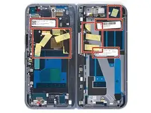
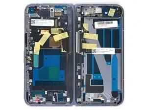
Remove any of the white stickers and yellow tape from your replacement inner screen assembly.
-
-
-
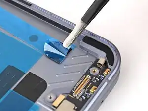
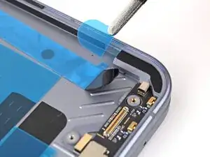
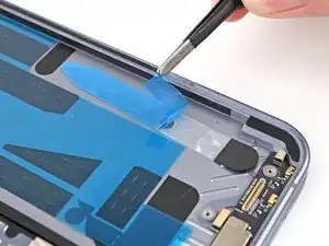
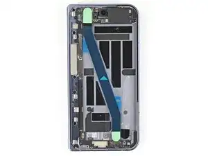
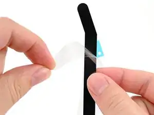
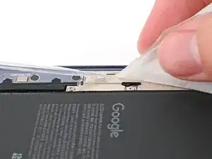
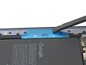
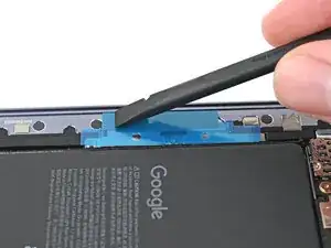
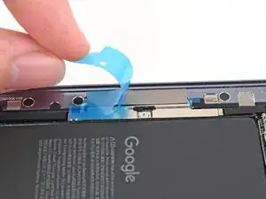
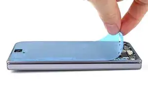
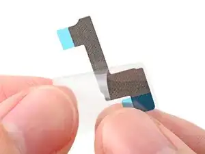
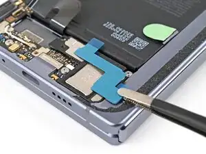
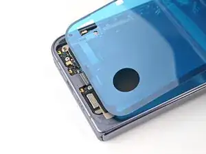
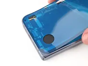
Use tweezers to remove the blue liner from the bottom of the black pull tab.
-
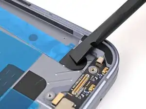
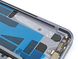
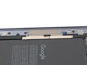
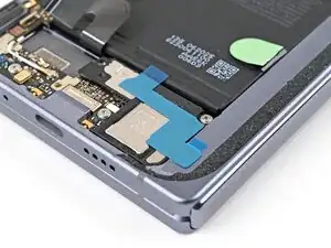
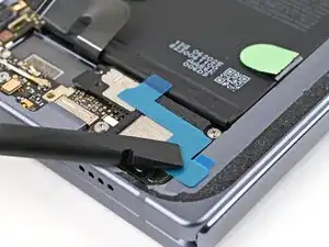
Press the pull tab down to adhere it to the frame.
-
-
-
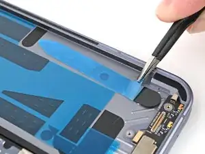
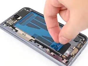
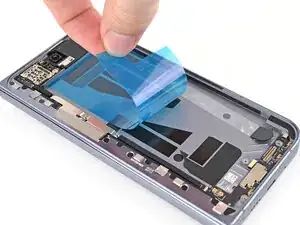
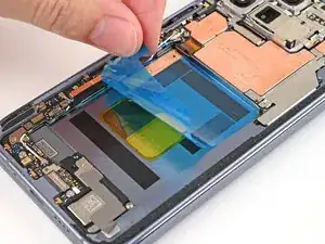
Use your fingers, or tweezers, to remove the large blue liner from the main flip battery adhesive strip.
-
-
-
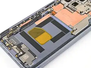
Before removing any liners, check that your flip battery jacket matches the size and shape of the cutout in the frame.
-
-
-
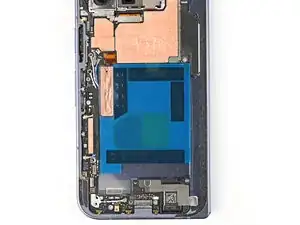
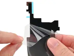
Peel off the flip battery jacket from its clear liner.
-
Align the jacket so it doesn't overlap with the flip battery adhesive.
-
Lay the jacket on the frame.
-
-
-
Use the flat end of a spudger, or your fingers, to press down the jacket and adhere it to the frame.
-
-
-
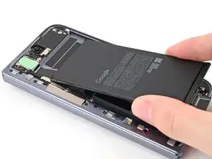
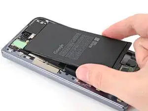
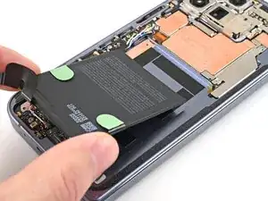
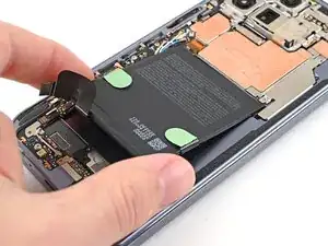
Align the top edge of the flip battery with the top edge of the battery well.
-
Lay the battery over the frame.
-
-
-
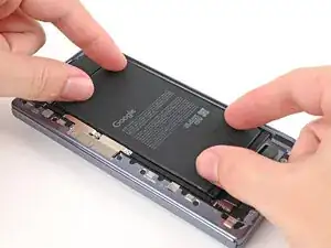
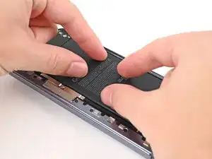
Press down along the perimeter of the flip battery to adhere it to the frame.
-
Let the phone sit for an hour for the adhesive to cure.
-
-
-
Remove any liners covering the upper board adhesive.
-
Place the upper board into its slot in the frame and press it down so it sits flat.
-
-
-
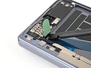
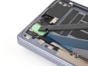
Use a spudger to press the green tab near the SIM card tray against the edge of the flip battery well.
-
Slide the spudger across the green tab to smooth out and adhere it against the SIM card tray.
-
-
-
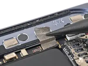
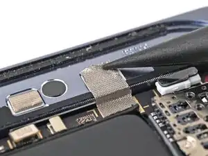
Use the point of a spudger to press the upper board conductive fabric onto the left edge of the frame.
-
-
-
Place the rubber spacer onto its spot on the upper board, making sure it sits between its gold outlines on the board.
-
-
-
Remove any liners covering the lower board adhesive.
-
Place the lower board into its slot on the frame.
-
-
-
Use your finger to press down the bottom left corner of the lower board and slot it into its alignment peg.
-
-
-
Use your fingers to press down the bottom right corner of the lower board to engage its grounding clips and thread it through its screw post.
-
-
-
Use the point of a spudger to press the lower board conductive fabric onto the left edge of the frame.
-
-
-
Place the rubber spacer onto its spot on the lower board, making sure it sits between its gold outlines on the board.
-
-
-
Use a Torx Plus 3IP driver to install the two 2.8 mm‑long screws securing the interconnect cable bracket.
-
-
-
Before removing any liners, check that both of your conductive fabric matches the size and shape of the interconnect cable bracket.
-
-
-
If there's adhesive residue on the interconnect cable bracket, use isopropyl alcohol (>90%) and a lint-free cloth to remove it.
-
-
-
Peel off the conductive fabric from its clear liner.
-
Align the fabric with the outer edge of the interconnect cable and the white outline on the frame.
-
Press the fabric to the bracket, making sure it overlaps onto the frame.
-
-
-
Use the flat end of a spudger, or your fingers, to press down the conductive fabric and adhere it to the frame.
-
-
-
Use the flat end of a spudger, or your fingers, to press down the conductive fabric and adhere it to the interconnect cable bracket.
-
-
-
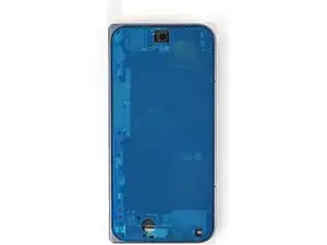
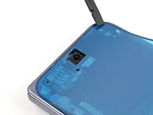
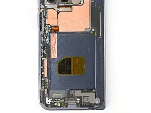
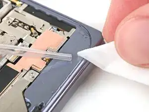
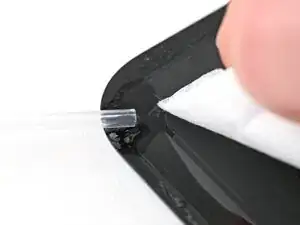
Use a spudger, or your fingers, to remove the old outer screen adhesive on the frame.
-
Use isopropyl alcohol (>90%) and a coffee filter or a microfiber cloth to remove any adhesive residue.
-
-
-
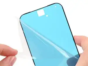
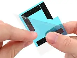
Peel away the top half of the new adhesive strip from its clear liner and keep the liner folded before continuing.
-
-
-
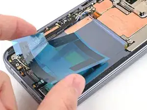
Align the top half of the adhesive over the frame, using the corners as reference points.
-
Place the adhesive on the frame.
-
-
-
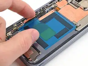
Use the flat end of a spudger, or your fingers, to press down the top edge of the adhesive and adhere it to the frame.
-
-
-
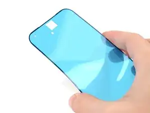
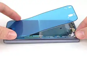
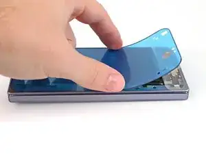
While peeling away the rest of the clear liner, slowly lay the adhesive over the perimeter of the phone.
-
-
-
Use the flat end of a spudger, or your fingers, to press down the rest of the adhesive and adhere it to the frame.
-
-
-
Use the point of a spudger to pry up the segmented tab on the bottom edge of the large blue liner.
-
-
-
Support the screen with your hand or prop it up on something sturdy.
-
Reconnect the outer screen cable press connector.
-
-
-
Use a Torx Plus 3IP driver to install the three screws securing the display cable bracket:
-
One 1.8 mm‑long screw
-
Two 2.5 mm‑long screws
-
-
-
Use tweezers to grip the pull tab of the secondary liner at the bottom left corner of the phone.
-
-
-
While holding the screen over the frame, peel the liner from the right and bottom edge of the frame and expose the adhesive.
-
-
-
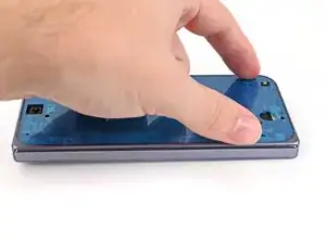
Press along the perimeter of the outer screen to adhere it to the frame.
-
Let the phone sit a few hours for the adhesive to cure.
-
-
-
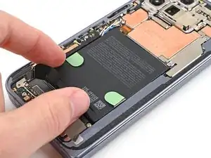
Use tweezers, or your fingers, to remove the old base battery adhesive from the frame.
-
Apply isopropyl alcohol (>90%) and use a coffee filter or microfiber cloth to clean any adhesive residue.
-
-
-
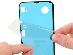
Before removing any liners, check that your base battery adhesive matches the size and shape of the cutout in the frame.
-
-
-
Peel off the adhesive strip from its clear liner.
-
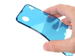
Align the adhesive strip with the top right corner of the base battery recess and press it onto the frame.
-
-
-
Use the flat end of a spudger, or your fingers, to press down the adhesive strips and adhere them to the frame.
-
-
-
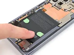
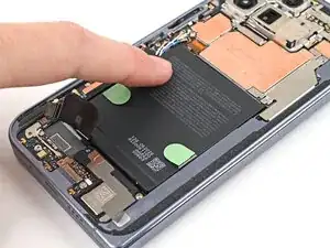
Align the new base battery with the top edge of the battery recess and press it to the frame.
-
-
-
Use your fingers to press along the battery to adhere it to the frame.
-
Let the phone sit for an hour for the adhesive to cure.
-
-
-
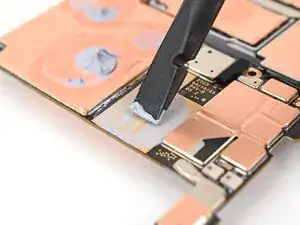
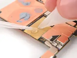
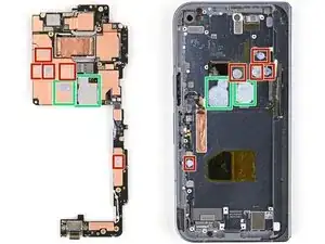
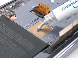
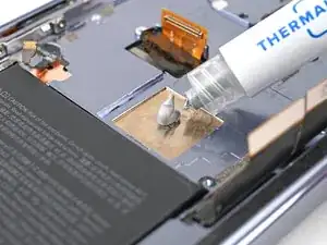
Apply thermal paste (seven total) to the motherboard in the same locations as the old thermal paste:
-
Five small beads of thermal paste
-
Two larger, "pea-sized" beads of thermal paste
-
-
-
Place the logic board back into its cutout in the frame, making sure no cables get trapped underneath it.
-
While pushing the logic board toward the bottom edge of the phone, press the logic board into its alignment pegs.
-
-
-
While using one hand to press down the thin vertical section of the logic board, use your other hand to press on the top section of the logic board against the left edge of the frame and engage its grounding clip.
-
Press the logic board straight down to slot it into its alignment peg.
-
-
-
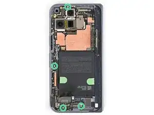
Use a Torx Plus 3IP driver to install the four 2.8 mm‑long screws securing the logic board.
-
-
-
Use the point of a spudger to press down the bracket and slide its plastic clip into the left edge of the frame.
-
-
-
Use a Torx Plus 3IP driver to install the 2.8 mm‑long screw securing the inner display connector bracket.
-
-
-
While pressing the bracket to the frame, use a Torx Plus 3IP driver to install the two 2.8 mm‑long screws securing the interconnect cable bracket.
-
-
-
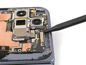
Use a spudger to press the antenna down into its thermal pad so it sits flat in the frame.
-
-
-
Slide the clip at the top right of the antenna bracket under the frame.
-
Press the bracket flat to the logic board and align its screw holes.
-
-
-
While pressing the bracket against the logic board, slide the top left clip under the frame.
-
-
-
Use a Torx Plus 3IP driver to install the three screws securing the antenna bracket:
-
One 1.9 mm‑long screw
-
Two 2.8 mm‑long screws
-
-
-
Remove any liners covering the inner front camera recess.
-
Place the inner front camera over its slot in the frame and press it down to adhere it.
-
-
-
Insert the loudspeaker at an angle into the bottom of the frame and press down to secure it.
-
-
-
If there's some adhesive residue left on the loudspeaker, use isopropyl alcohol (>90%) and a coffee filter or a microfiber cloth to remove it.
-
-
-
Peel off the clear liner on the top loudspeaker conductive fabric.
-
Place the conductive fabric over its spot on the loudspeaker.
-
-
-
Use the flat end of a spudger or your fingers to press down the conductive fabric and adhere it.
-
-
-
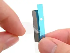
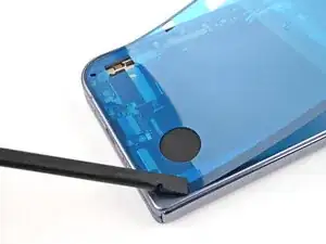
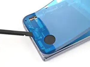
Remove the small, rounded blue liner on the underside of the tape.
-
Press down the fabric so it adheres to the frame.
-
-
-
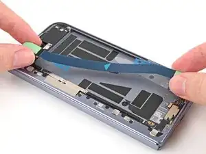
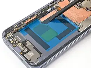
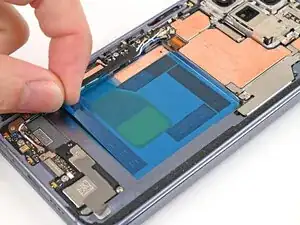
Peel the clear liner off your replacement graphite sheet to expose the adhesive on the upper half.
-
Align the upper half of the graphite sheet over the logic board and lay it down.
-
-
-
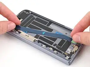
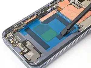
Use the flat end of your spudger or your finger to press down the upper half of the graphite sheet and secure it to the logic board.
-
-
-
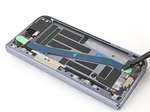
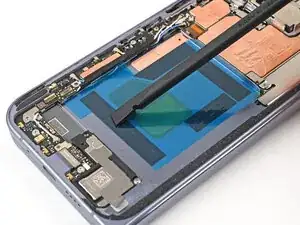
Drag a spudger or your finger from the middle section of the graphite sheet to the adhesive section over the loudspeaker to flatten the graphite sheet and adhere it.
-
-
-
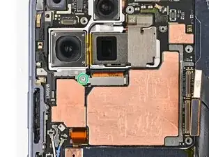
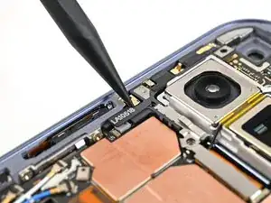
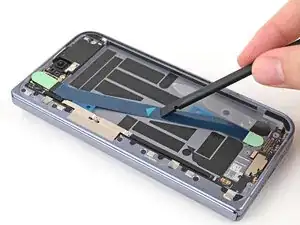
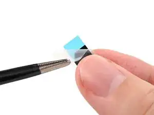
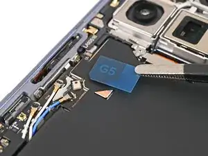
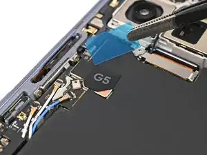
Remove the clear liner from the G5 sticker.
-
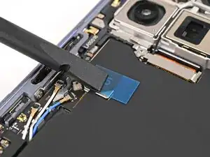
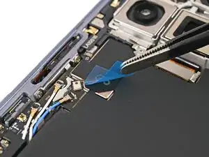
Place the G5 sticker over the graphite sheet so its slanted edge lines up with the small copper triangle.
-
Use a spudger or your finger to press down the sticker and adhere it.
-
-
-
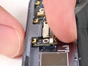
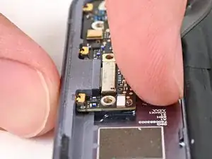
Use tweezers to slide the left edge of the vibrator into its clip and rest it in its cutout in the frame.
-
-
-
Use isopropyl alcohol (>90%) and a coffee filter or a microfiber cloth to remove any adhesive residue.
-
-
-
Peel away the bottom half of the new adhesive strip from its clear liner and keep it folded before continuing.
-
-
-
Align the bottom half of the adhesive over the frame, using the corners as reference points.
-
Place the adhesive on the frame.
-
-
-
Use the flat end of a spudger, or your fingers, to press down the bottom edge of the adhesive and adhere it to the frame.
-
-
-
While peeling away the rest of the clear liner, slowly lay the rest of the adhesive over the perimeter of the phone.
-
-
-
Use the flat end of a spudger, or your fingers, to press down the rest of the adhesive and adhere it to the frame.
-
-
-
Use a spudger to pry up the segmented tab on the bottom right corner of the large blue liner.
-
-
-
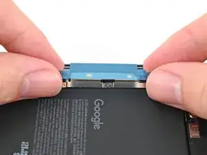
Use a spudger or your finger to push the bracket upwards and slide its clip under the top edge of the frame.
-
-
-
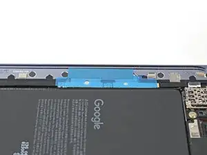
Use a Torx Plus 3IP driver to install the three 3.0 mm‑long screws securing the top bracket.
-
-
-
While holding the back cover over the frame, peel the liner from the left and top edge of the frame and expose the adhesive.
-
-
-
Press along the perimeter of the back cover to adhere it to the frame.
-
Let the phone sit a few hours for the adhesive to cure.
-


Congratulations on completing your repair!
Calibrate your newly installed batteries after completing this guide.
Take your e-waste to an R2 or e-Stewards certified recycler.
Repair didn’t go as planned? Try some basic troubleshooting, or ask our Google Pixel 10 Pro Fold Answers Community for help.