Introdução
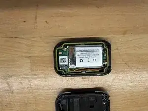
The ARMTE-001 is the WIFi remote for an older model GoPro, GoPro 3 or 4.
In my case it controls a GoPro Hero3. The original battery would hold a charge for ~30 minutes in cold weather then die, so I needed to replace the battery.
You will need to pry the battery off the circuit board, and re-solder three cables. If you aren't happy with this, you shouldn't attempt it.
Peças
-
-
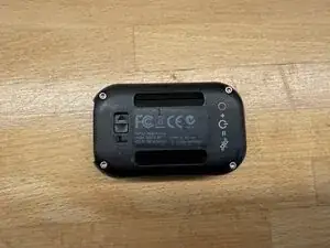
GoPro Hero3/Hero4 family WiFi remote control
-
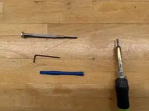
Tools needed. Small hex screwdriver, 1.5mm Hex driver, spudgers, soldering iron and solder
-
-
-
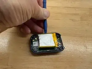
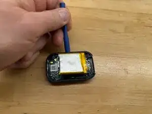
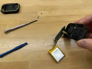
REMEMBER THAT BATTERIES CAN CATCH FIRE IF NOT PROPERLY HANDLED. BE GENTLE when prying up the old battery. DO NOT PIERCE IT.
-
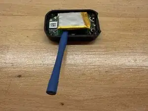
Using a spudger carefully pry either side of the battery from the circuitboard, until it comes off.
-
BE CAREFUL NOT TO PIERCE the old battery (I know I’m saying it again!)
-
-
-
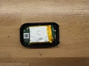
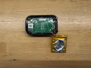
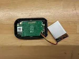
Once the battery is off, there are three small screws holding the circuit board in place. Top left, Top right and bottom right in the first photo.
-
Remove the three screws, then with a spudger gently pry up the circuit board from the hole where the cables go in.
-
At the bottom left there is a small plastic clip you have to lift the board away from this.
-
Underneath the board, is a ribbon cable to the display. Don't disturb this, you don't need to disconnect it as the board will swing up and out. See the last photo.
-
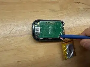
Unsolder the three connections. Noting which colour wire goes to which pin.
-
The replacement battery will have a small cover over the red (+) terminal.
-
Solder the black (-) connection first, then the white/yellow, then remove the cover from the red (+) cable being careful not to short it anywhere on the board and solder it last. Check your connections.
-
-
-
Now it is time to re-assemble.
-
Slide the board back into the case, being careful not to damage the ribbon cable to the display. There is a plastic clip at the bottom left of the first picture, you must ensure the board goes under this, then the board will lie flat in the case.
-
Replace the three screws
-
Check the board is level in the case, and that it is not resting on the plastic clip at the bottom left.
-
Place the battery on the top, and check the cover fits without the seal in place. You can tuck the wires alongside the battery.
-
-
-
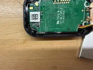
Using a small piece of flat double sided tape stick the battery to the board. I placed the battery as far as I could to the top of the case, and to the right of the white line on the left by the QR code
-
NOTE that the battery MUST NOT cross the white line beside the QR code or the case will not close.
-
Replace the seal into the case. It only fits one way around as the cutouts are different sizes, be careful to ensure it is level, not twisted and even.
-
-
-
Replace the cover carefully, checking it is even and not resting on anything
-
Finally with the 1.5mm hex driver, replace the screws. Tighten then top left then bottom right, the top right and finally bottom left. Don't overtighten.
-
This is not complex, but requires soldering skills, and a bit of patience.
Good luck!