Introdução

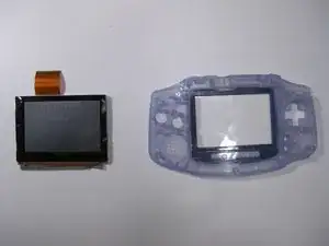
Use this guide to remove the LCD screen from the Game Boy Advance.

  1. W5xHDkFFxsZPAfqJ
    W5xHDkFFxsZPAfqJ
    YLRFrpXTUJnvKIMt
    sVYy54cZhr1yVDYY
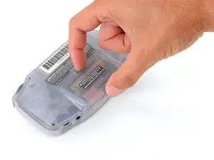
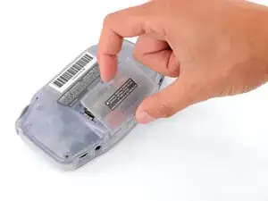
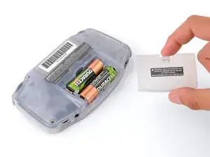
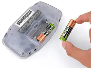
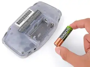
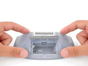
    • Release the battery cover tab with your finger and swing the cover away from your Game Boy to remove it.

    • During reassembly, insert the tabs on the bottom edge of the cover into their cutouts and press the cover into place.

  2. maxmprfVqllPKMpO
    maxmprfVqllPKMpO
    IWHASUO3UyEVPZNr
    lLsZLi2bYgQJgD5N
    • Remove the two AA batteries.

    • If the metal terminals are corroded, follow this guide to clean them.

    • When installing batteries, use the diagram in the battery well to properly orient them.

  3. h2MTNWGvbhaMV3al
    h2MTNWGvbhaMV3al
    ADgFcLpctBX6Itv2
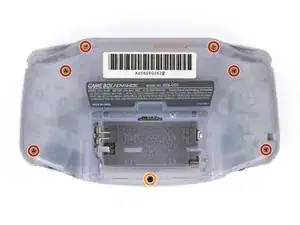
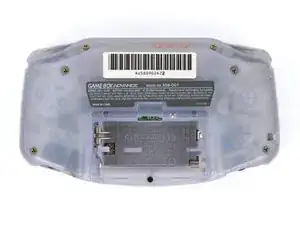
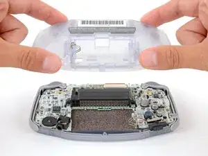
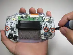
    • Remove the seven screws securing the back shell:

    • Six 9.4 mm‑long tri‑point Y0 screws

    • One 8.5 mm‑long JIS 1 screw

    • You can try to use a non-iFixit Phillips driver in a pinch, but you risk damaging or stripping screws. Push down firmly on the driver and twist slowly.

  4. VETTuXWgjPcRKRfw
    VETTuXWgjPcRKRfw
    4QEfBiByXkhUWxru
    • Lift the back shell straight up and remove it.

    • During reassembly, squeeze the shell firmly around the edges and ensure the shoulder buttons and bumpers are properly seated with no large gaps. Gently test the buttons to make sure everything feels correct.

  5. WkkQIbeHrTlfEGGI
    WkkQIbeHrTlfEGGI
    X3pRpCLRTJHLWFRj
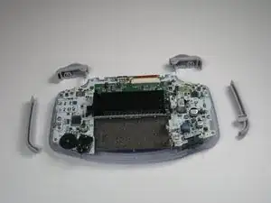
    • Remove left and right triggers by lifting and pulling them away from the system.

    • Do the same for side panels

    • For finicky or jammed triggers only! Adjust and correct triggers and reassemble. Most jammed triggers are caused by buttons misplaced or jammed in its enclosure.

    my side pannel on the right is a little loose how do i fix it

    Mark -

  6. RRebCeaukHvKwKfZ
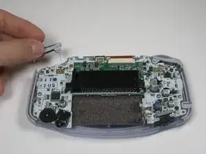
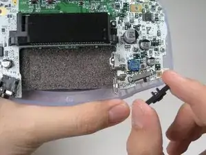
    • Remove the gray On/Off Switch by pulling up and away from the unit. Replace with another switch if necessary.

  7. JvCo1AeCraFKyq3u
    • Remove the three screws on the circuit board with a Phillips #1 screw driver.

  8. Zt5QVxBOF3KYi6nk
    Zt5QVxBOF3KYi6nk
    pYOYGdlqudvRSNjS
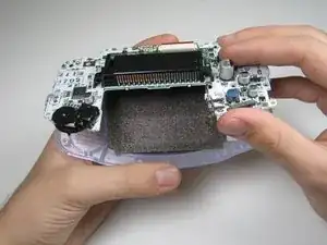
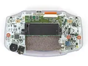
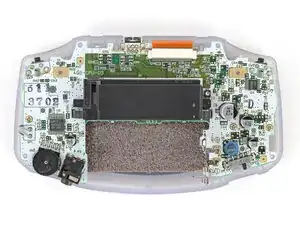
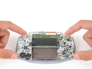
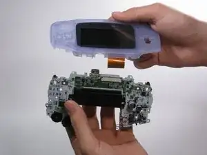
    • Pull circuit board away from the front panel by pulling up at the bottom of the circuit board, keeping the top ribbon still connected.

    • Handle with care! The ribbon connecting the circuit board to the LCD screen can easily be damaged and will require replacement if broken.

  9. 5tEpJXH3m4wDxPaC
    5tEpJXH3m4wDxPaC
    EiAOwtUZ3yLrSXm1
    • Use a JIS 1 screwdriver to remove the three 7 mm‑long screws securing the motherboard.

  10. ReHAqtiMKXDVFsGt
    ReHAqtiMKXDVFsGt
    xCFRKKFnKnLWK34T
    QZnuouF61ONGVTtG
    • Be careful not to strain the screen cable that connects the motherboard.

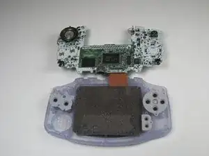
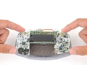
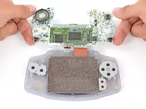
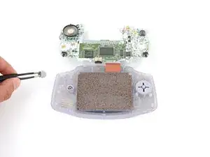
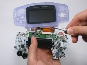
    • Carefully flip the motherboard over the top edge of your Game Boy and rest it on your work surface.

    • During reassembly, make sure the speaker gets correctly slotted into its circular cutout (including a small tab on the bottom) when lowering the motherboard into place.

  11. 1T4wUG4d2ZMSUQCD
    1T4wUG4d2ZMSUQCD
    pdCyUMpWQjiomdmH
    oQOA3UAMXUdCIcwP
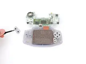
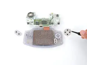
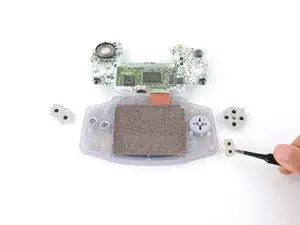
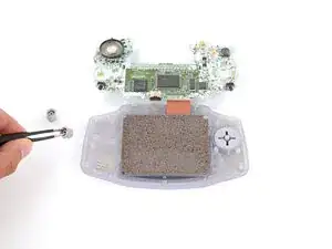
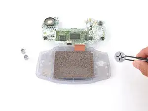
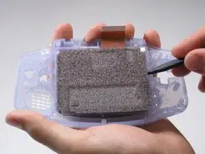
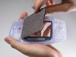
    • Use tweezers or your fingers to remove the three silicone pads covering the buttons (A and B, the D‑pad, and Start/Select ).

    • If any of the pads are missing, they may be stuck to their corresponding spot on the motherboard.

    • During reassembly, use your fingers to press each pad into place, using the alignment pegs to properly orient them.

  12. 1O3ePNJpLPhudCxZ
    1O3ePNJpLPhudCxZ
    WJk4HAhEIGFdOLKA
    YSUKlNTASWCD3Vuj
    • Use tweezers or your fingers to remove the buttons (A and B as well as the D‑pad).

    • The Start/Select buttons are part of the silicone pad—there are no other buttons to remove.

    • When re‑inserting the action buttons, note that each one is keyed specifically for its recess and proper orientation.

  13. UhZNRtFqNC2lxuSa
    UhZNRtFqNC2lxuSa
    24gSaiyjo13FyyeS
    kwui2hPRIwGoHia6
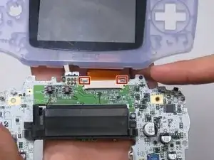
    • Use a spudger/tweezers/fingernail to unlatch the LCD ribbon port by pulling the grey tabs on the sides upwards (towards the top edge of the PCB).

    • Once the LCD ribbon port has been unlatched, the LCD ribbon should very easily slide out and can be removed with zero force using fingers or tweezers.

  14. TXIA3YTHCeXgl1xj
    TXIA3YTHCeXgl1xj
    L1OZTSnJalEbeuMp
    LJfaU6K2mCebAmKX
    • Use the spudger to lift the screen from the front panel. Place the spudger in the space directly left of the D-pad.

    • The screen and the front panel is connected by a black tape that could rip if not removed carefully.

    Friendly warning. My LCD screen broke during this step. The tape can really hold it in there.

    Chris Raybould -

    So do I! So the best solution to avoid it is to airdry the front cover to melt glue...

    Nicolas Puyet -

Conclusão

To reassemble your device, follow these instructions in reverse order.

Aldo Corona

Membro desde: 26/01/10

886 Reputação

0 comentários