Introdução
This guide shows technically-skilled users how to expose and lift out the complete heat pump module in the GE Ultrafast washer-dryer combo. Doing so lets you clean, inspect, or replace the assembly, but it can void the five-year heat-pump warranty and should only be attempted with proper ESD protection and thorough screw organization.
-
-
Pull each dispenser drawer fully forward until it stops.
-
Depress the rear tab on each drawer and slide the drawer completely out of the console.
-
-
-
Locate four recessed Phillips screws above the filter opening and one in the lower-left corner.
-
Remove the five screws; the lower screw may need a thicker number two driver.
-
-
-
Pull the filter carriage forward, press the left-side tab, and withdraw the entire filter assembly.
-
-
-
Grip the console near the dispenser cut-out, pull it forward, then lift upward to free its tabs.
-
-
-
Unplug the four highlighted harnesses from the console, leaving the optional red harness engaged unless removal is required.
-
Separate the door-light harness by pressing its clip and pulling straight out.
-
-
-
Remove seven Phillips screws securing the blue top to the gray heat shield—two left, three rear, two right.
-
Slide the cover forward then lift it clear, releasing the sides if they catch.
-
-
-
Compress the spring clamp on the front fill hose with pliers and pull the hose free, using towels to catch residual water.
-
Cut the factory cable ties securing the fill tube and adjacent wire trunk.
-
-
-
Remove five screws around the outer heat shield.
-
Cut any ties anchoring wires to the shield to allow removal.
-
Remove two screws on each side of the upper metal bracket and lift the bracket out, exposing the heat pump.
-
-
-
Cut the tie securing the dispenser harness and unplug the connector.
-
Squeeze clamps and slide the four visible water hoses off the rear barbs, prying gently with a flat screwdriver if stuck.
-
Unclip and remove the snake-shaped overflow hose from its retainers and the dispenser.
-
Slide the dispenser rearward, lift it, then detach the large tub hose underneath using pliers on the clamp.
-
-
-
Remove three Phillips screws securing the top NTC sensor and lift the sensor straight out.
-
Release any cable ties restraining the sensor harness.
-
-
-
Unscrew and slide off the control board cover.
-
Cut the large cable trunk tie, slide the board rearward out of its slots, and remove it from the cabinet.
-
-
-
Unscrew the two bottom screws, flex the top tabs, and lift the metal cover off the inverter board.
-
Press the center latch on each large harness before disconnecting and remove all remaining connectors.
-
Cut any retaining ties and remove the single board mounting screw.
-
Slide the board to the right to free it from its slots and lift it out.
-
-
-
Cut or release all cable ties attaching blower motor wiring and other harnesses to the heat pump top and rear.
-
-
-
Remove two Phillips screws anchoring the blower motor, then pull the motor top outward to disengage hidden lower screws.
-
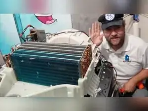
Lift the plastic cover straight off to expose coils and internals.
-
-
-
Loosen the clamp on the large air inlet hose at the dispenser side and release its side tabs.
-
Loosen, but do not remove, the blower duct clamp on the front right side.
-
Loosen the condensate hose clamp under the water valves.
-
Remove the green ground screw securing the compressor strap to the chassis.
-
Cut the push-mount cable ties securing the main wire trunk to free the assembly.
-
-
-
Remove six Phillips screws holding the heat pump: two by the dispenser opening, two on the front frame, and two on the control board side.
-
The heat pump system is now fully removed and accessible for servicing or replacement. Reverse the procedure to reinstall, matching each harness, hose, and screw to the organizer notes, and reattach all cable ties to maintain airflow and safety grounding.