Introdução
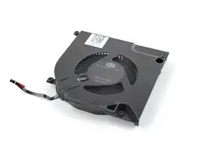
Use this guide to remove and replace one or both of the Graphics Module Fans in your Framework Laptop 16.
The guide shows replacing the right Graphics Module Fan, but the procedure is identical to replace the left fan.
-
-
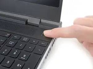
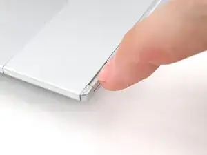
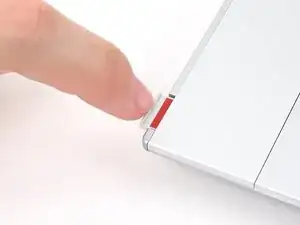
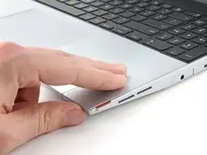
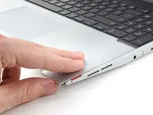
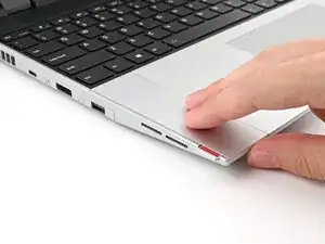
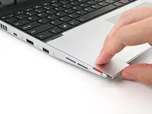
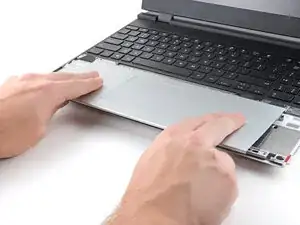
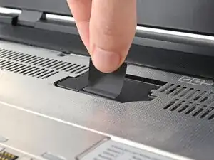
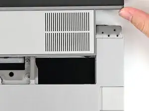
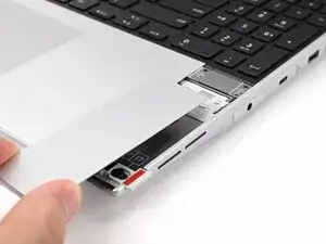
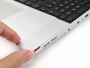
Use your fingers to slide the Touchpad Spacer toward the bottom edge of the laptop and unclip it.
-
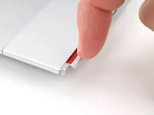
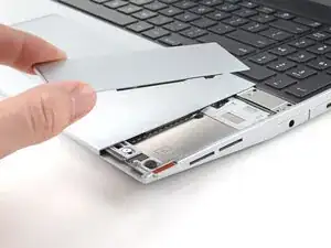
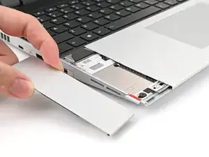
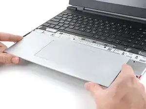
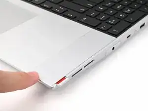
Lift the Touchpad Spacer off the laptop and remove it.
-
-
-
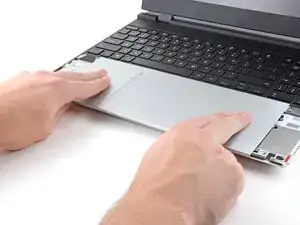
Use your fingers to slide the Touchpad Module toward the bottom edge of the laptop and disconnect it.
-
Lift the Touchpad Module and remove it.
-
-
-
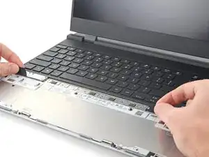
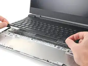
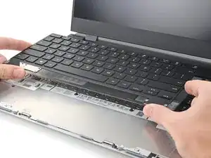
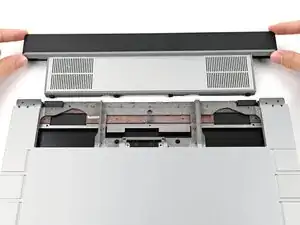
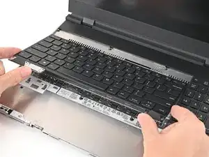
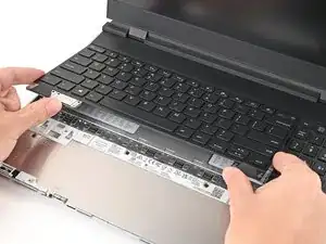
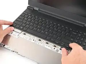
Grip the two pull tabs along the bottom of the keyboard and lift until its magnets release.
-
Remove the keyboard.
-
-
-
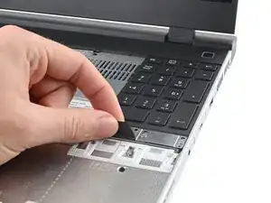
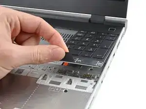
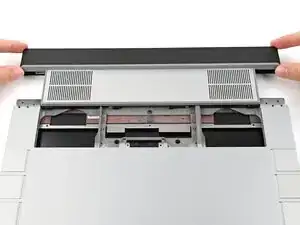
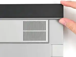
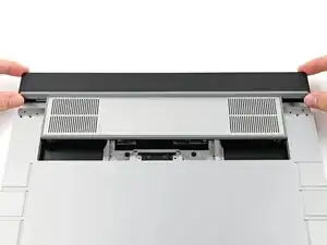
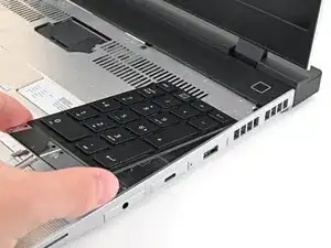
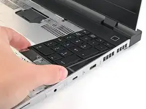
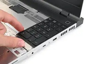
Grip the pull tab at the bottom of the Input Module and lift until its magnets release.
-
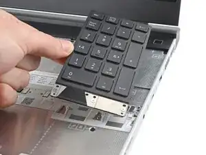
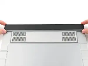
Remove the Input Module.
-
Repeat for any remaining Input Modules.
-
-
-
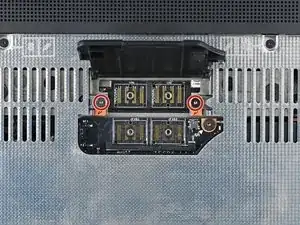
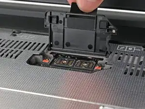
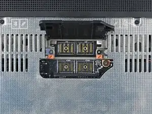
Use your Framework Screwdriver to loosen the four captive T5 Torx screws securing the interposer.
-
-
-
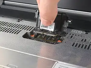
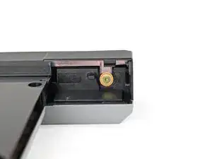
Use your Framework Screwdriver to loosen the two captive T5 Torx screws securing the Graphics Module.
-
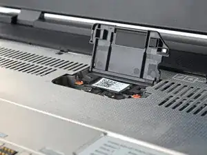
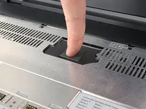
Close the interposer door before continuing.
-
-
-
Close your laptop and flip it over.
-
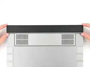
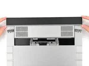
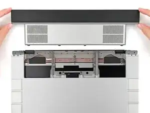
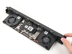
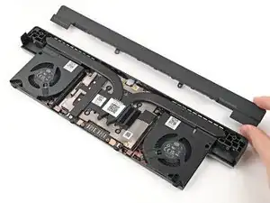
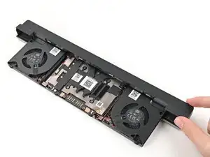
Slide the Graphics Module out of the laptop and remove it.
-
-
-
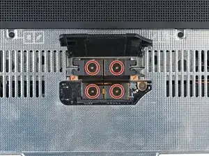
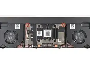
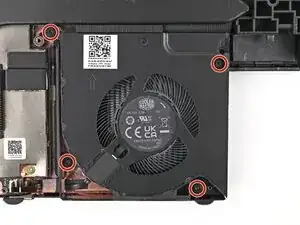
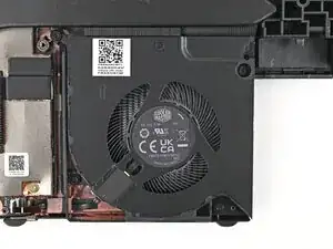
Use your Framework Screwdriver to remove the four 3.6 mm‑long T5 Torx screws securing the Graphics Module cover:
-
Two screws on the flat surface of the module, next to the fans.
-
Two screws on the thin edge of the module, near the ends. You'll need to flip the module on its back edge to access them.
-
-
-
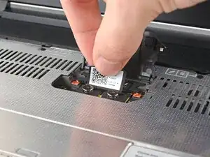
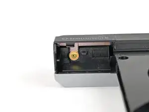
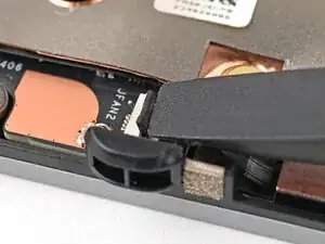
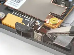
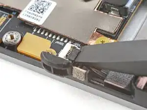
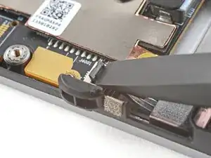
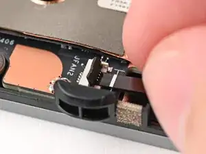
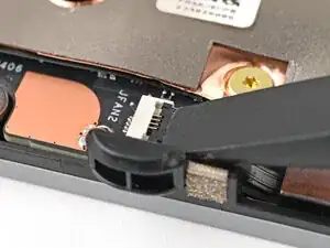
Use the flat end of a spudger, or a clean fingernail, to lift up and release the locking tab on the fan ZIF connector.
-
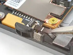
Use your fingers to grip the brown pull tab and slide the fan cable straight out of its socket.
-
-
-
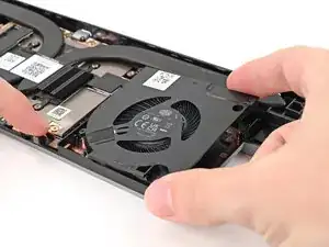
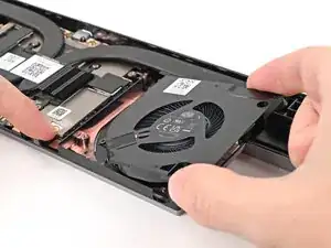
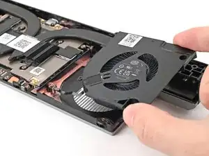
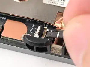
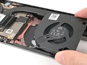
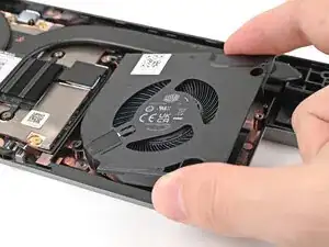
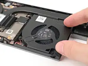
Use one hand to press the fan cable flat to the module.
-
Use your other hand to pull the fan out of its housing, making sure to thread the cable though its slot.
-
Remove the fan.
-
-
-
Congratulations on completing disassembly! The remaining steps will show how to reassemble your Framework Laptop.
-
-
-
Use your Framework Screwdriver to install the four 3.6 mm‑long T5 Torx screws securing the Graphics Module cover:
-
Two screws on the flat surface of the module, next to the fans.
-
Two screws on the thin edge of the module, near the ends. You'll need to flip the module on its back edge to access them.
-
-
-
Use the flat end of a spudger, or a clean fingernail, to lift up and release the locking tab on the fan ZIF connector.
-
-
-
Use your fingers to grip the brown pull tab and slide the fan cable straight into its socket.
-
Use the flat end of your Framework Screwdriver, or a clean fingernail, to press down the locking tab on the fan ZIF connector.
-
-
-
Flip over the laptop and open it.
-
Lift the interposer door by its black pull tab and let it rest upright.
-
-
-
Use your Framework Screwdriver to tighten the two captive T5 Torx screws securing the Graphics Module.
-
-
-
Use your Framework Screwdriver to tighten the four captive T5 Torx screws securing the interposer.
-
Close the interposer door.
-
-
-
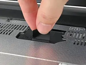
Grip the pull tab at the bottom of the numpad.
-
Lift the pull tab until the numpad magnets release.
-
Remove the numpad.
-
-
-
Align the top edge of the keyboard with the top edge of the laptop.
-
Lay the keyboard on the laptop and let the magnets pull the keyboard into place
-
-
-
Place the Touchpad Spacer over its spot on the laptop with the bottom edge overhanging slightly.
-
Slide the Touchpad Spacer towards the top of the laptop to secure it.
-
Repeat the same procedure for the other Touchpad Spacer.
-


You finished fixing your Framework Laptop!
Take your e-waste to an R2 or e-Stewards certified recycler.
If you need help, contact Framework support.