Introdução

Use this guide to remove and replace the Expansion Bay Shell Fan Board in your Framework Laptop 16.

  1. FyZqYQXlGGSUVdfO
    • Unplug all cables and fully shut down your laptop.

  2. KX6SbVDOSK11tpww
    KX6SbVDOSK11tpww
    xUsiPWFWSHywwlyH
    YUTaVvGIQMvEBoVL
    • Use your fingernail to pull out the two Input Module latches and unlock them.

    • The latch will show red if it's unlocked.

  3. SJk2GqymsGfFPtk6
    SJk2GqymsGfFPtk6
    qYPAIGK4ZAN1UcxK
    RJPENmljQ6MIcvnN
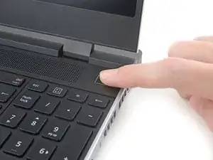
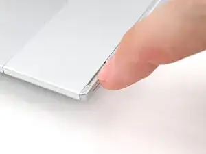
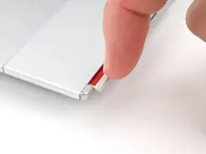
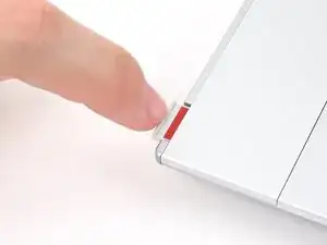
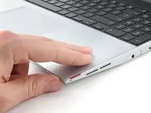
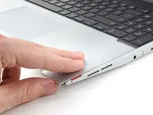
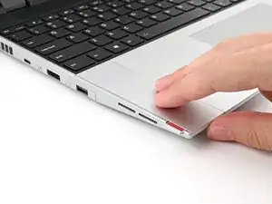
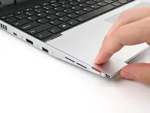
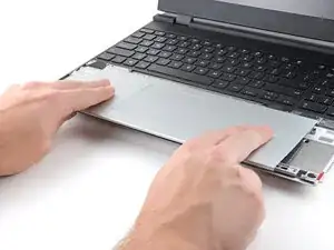
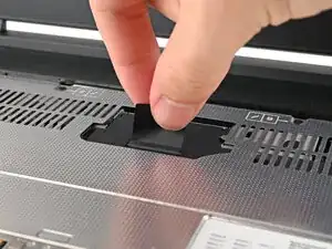
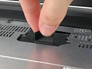
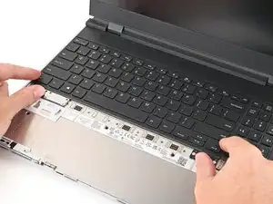
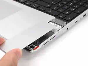
    • Use your fingers to slide the Touchpad Spacer toward the bottom edge of the laptop and unclip it.

    • If you're having trouble, check if the corresponding Input Module latch is properly unlocked.

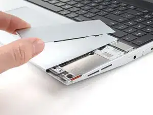
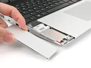
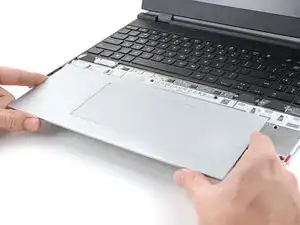
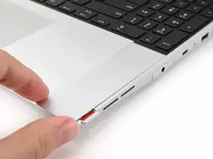
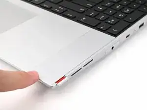
    • Lift the Touchpad Spacer off the laptop and remove it.

  4. jNWbnEQoPE1b5FNs
    jNWbnEQoPE1b5FNs
    T4eCedmNWxtIK3E4
    qMrYphKZARGoeODv
    • Repeat the same procedure for the other touchpad spacer.

  5. yYIvnKNYAZ5ZR5Cw
    yYIvnKNYAZ5ZR5Cw
    1OO4eJ2caggITR13
    fbmNJeKVP62XPULp
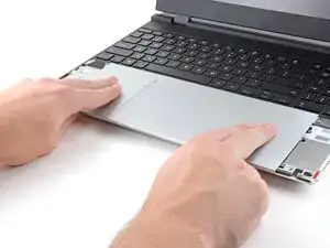
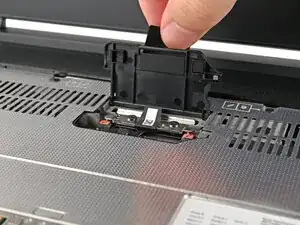
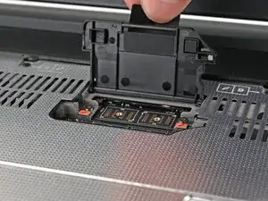
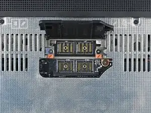
    • Use your fingers to slide the Touchpad Module toward the bottom edge of the laptop and disconnect it.

    • If you're having trouble, check if the Input Module latches are properly unlocked.

    • Lift the Touchpad Module and remove it.

  6. WXjcPFl2MgDiX2PZ
    WXjcPFl2MgDiX2PZ
    PojU1s2ZQqyfYBvO
    YlWkflmfJPHDuZov
    • The keyboard is held in place with strong magnets. Apply gradually increasing force to avoid having the keyboard violently eject.

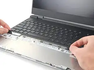
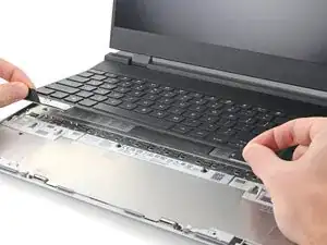
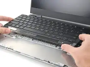
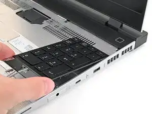
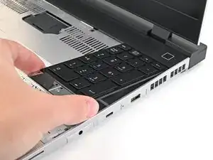
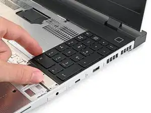
    • Grip the two pull tabs along the bottom of the keyboard and lift until its magnets release.

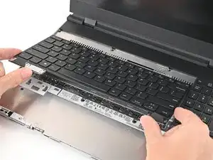
    • Remove the keyboard.

  7. hesMM66MFJtTfvCZ
    hesMM66MFJtTfvCZ
    3ZJ4rrrJTvR22eiV
    WesxvpHZwQSNZ3fK
    • Your Input Module(s) might be different, but the procedure to remove them is the same.

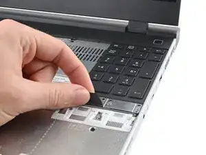
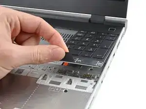
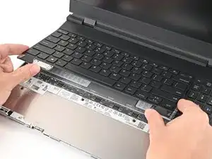
    • Grip the pull tab at the bottom of the Input Module and lift until its magnets release.

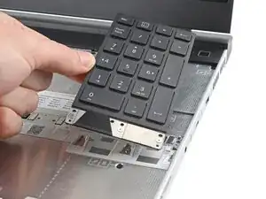
    • Remove the Input Module.

    • Repeat for any remaining Input Modules.

  8. QeHS6WfLKQkZDQc2
    QeHS6WfLKQkZDQc2
    PRVQKSIgYSUVLdRR
    • Lift the interposer door by its black pull tab and let it rest upright.

  9. YoVgKFeEsQXMNhdQ
    • Use your Framework Screwdriver to loosen the three captive T5 Torx screws securing the interposer.

  10. VbeICH26foiIQX1y
    VbeICH26foiIQX1y
    ZOHFCja6y3XAPUvh
    • Lift the interposer by its pull tab and remove it.

  11. 1xM31Q5HLnOx22yi
    1xM31Q5HLnOx22yi
    BFNZQlRYjBrJIHOJ
    • Use your Framework Screwdriver to loosen the two captive T5 Torx screws securing the Expansion Bay Shell.

    • Close the interposer door before continuing.

  12. sE5tn2AQHyQNOVLw
    sE5tn2AQHyQNOVLw
    Z3MgX33AEDpMPftD
    TgjsUMg1AquJLbig
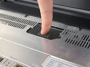
    • Close your laptop and flip it over.

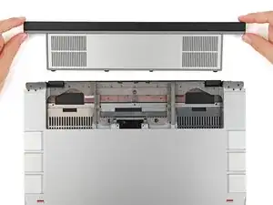
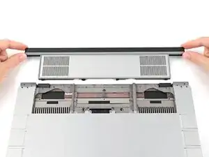
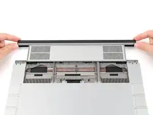
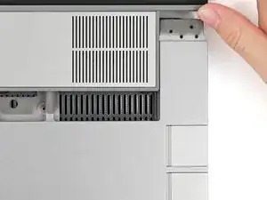
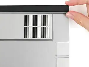
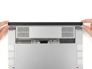
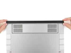
    • Slide the Expansion Bay Shell out of the laptop and remove it.

    • The shell should slide out easily. If you feel any resistance, check that the screws holding it in place are fully loosened.

  13. fXZVbwqRAF4QTmOy
    fXZVbwqRAF4QTmOy
    N1uBEYDajy4hICX2
    XfYCjXQXOAxGLXeq
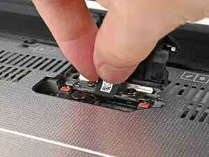
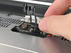
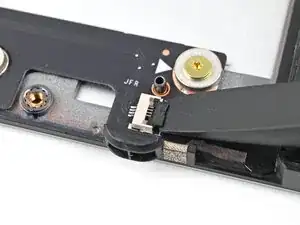
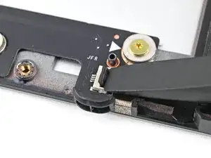
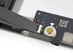
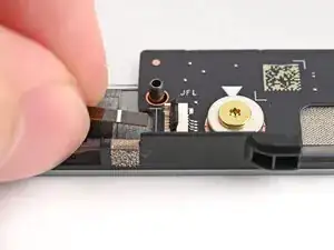
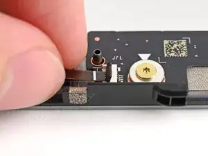
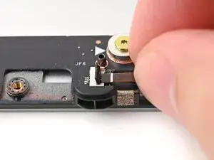
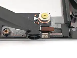
    • Use the flat end of your Framework Screwdriver, or a clean fingernail, to lift up and release the locking tab on the right fan ZIF connector.

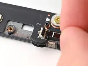
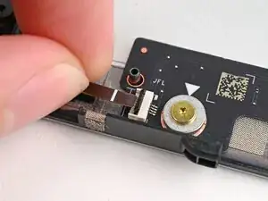
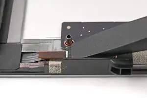
    • Use your fingers to grip the brown pull tab and slide the fan cable straight out of its socket.

  14. qdNYBhjAl5AwvQOG
    qdNYBhjAl5AwvQOG
    G1Xgu3bUO4qZRMu1
    MpnIMRGEkO4SITIf
    • Repeat the previous step to disconnect the left fan cable.

  15. gcK6AFSGRRhMVNET
    gcK6AFSGRRhMVNET
    CjWuDm3SIa5tfABt
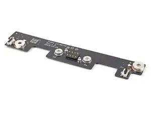
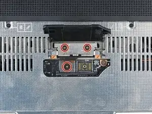
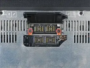
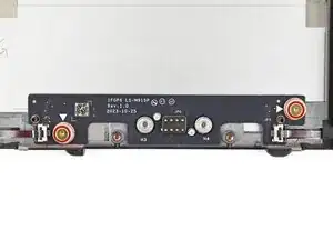
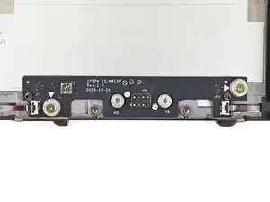
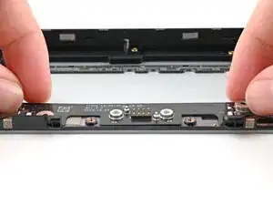
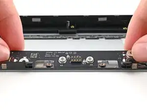
    • Use your Framework Screwdriver to remove the two 3.6 mm‑long screws securing the Expansion Bay Shell Fan Board.

  16. bfM6WpNdrrtIVbN3
    bfM6WpNdrrtIVbN3
    XKgQYLlDti1vc2ue
    dAie51S1T41AtYm1
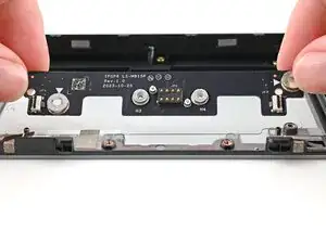
    • Use your fingers to lift the board straight off its alignment pegs on Expansion Bay Shell and remove it.

  17. yAqjOcYW4FxBfQJa
    • Congratulations on completing disassembly! The remaining steps will show how to reassemble your Framework Laptop.

  18. dAie51S1T41AtYm1
    dAie51S1T41AtYm1
    XKgQYLlDti1vc2ue
    bfM6WpNdrrtIVbN3
    • Place the board straight on its alignment pegs on Expansion Bay Shell.

  19. gcK6AFSGRRhMVNET
    gcK6AFSGRRhMVNET
    CjWuDm3SIa5tfABt
    • Use your Framework Screwdriver to install the two 3.6 mm‑long screws securing the Expansion Bay Shell Fan Board.

  20. nEYOVGYm3CE65TOi
    nEYOVGYm3CE65TOi
    q4fMSxUYiMY1PaTx
    GjbWqmhBLHXfeCXm
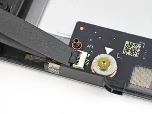
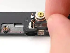
    • Use your fingers to grip the brown pull tab and slide the left fan cable straight into its socket.

    • Use the flat end of your Framework Screwdriver, or a clean fingernail, to press down the locking tab on the left fan ZIF connector.

  21. JdWmILx11AMUm6oX
    JdWmILx11AMUm6oX
    TCHJcFA2DNIFVr5R
    pNlJPfgfGScPFGWj
    • Repeat the previous step to connect the right fan cable.

  22. V2CUewD6OQVgUwNd
    V2CUewD6OQVgUwNd
    FoSxDsy2yMqYbeUQ
  23. Zr2QQpfkhSVod3Kf
    Zr2QQpfkhSVod3Kf
    LGc5pcnLKfPhWByF
    • When installing the shell, keep it level to the laptop so it doesn't buckle on the rails.

    • There should be no gaps between the laptop and the shell when it's installed correctly.

  24. ooBNeknaOCPUFU1v
    ooBNeknaOCPUFU1v
    sDAulYDvbkUhmtkD
    1SxGFxuPndBDqtxU
    • While keeping the shell level with the laptop, slide it into its slot.

    • The shell should slide in easily. If you feel any resistance, pull the module out and realign it.

    • You should hear an audible "click" when the shell's clips snap into place.

  25. EQEQPKRVMIg1UBvj
    EQEQPKRVMIg1UBvj
    gMTioMObSu3mGVHL
    • Flip over the laptop and open it.

    • Lift the interposer door by its black pull tab and let it rest upright.

  26. 1xM31Q5HLnOx22yi
    1xM31Q5HLnOx22yi
    K2msUAJei2QOCFTF
    • Use your Framework Screwdriver to tighten the two captive T5 Torx screws securing the Expansion Bay Shell.

  27. jtBYr4yZrlYPJnY3
    jtBYr4yZrlYPJnY3
    Y1nJArDJvjEfGvJp
    • Place the interposer over its spot between the Mainboard and the Expansion Bay.

  28. KxOrd3I1jabAB1ZY
    KxOrd3I1jabAB1ZY
    ny2MDHPvLAEQtmsl
    • Use your Framework Screwdriver to tighten the three captive T5 Torx screws securing the interposer.

    • Close the interposer door.

  29. JyccFC2cavJAQkw2
    JyccFC2cavJAQkw2
    UBPFtlfVJwD5MG4C
    qDoJmL3yEaNiGyLv
    • Your Input Module(s) might be different, but the procedure to remove them is the same.

    • Align the top edge of the Input Module with the top edge of the laptop.

    • Lay the Input Module on the laptop and let the magnets pull the keyboard into place

    • Make sure the Input Module is seated properly on its alignment pegs and sits flush with the edges of the laptop.

    • Repeat for any remaining Input Modules.

  30. 2oPYqKStliPhyMNB
    2oPYqKStliPhyMNB
    Sa6jykktBZSuiFBK
    mSXYbDZf6nqTloeB
    • Align the top edge of the keyboard with the top edge of the laptop.

    • Lay the keyboard on the laptop and let the magnets pull the keyboard into place

    • Make sure the keyboard is seated properly on its alignment pegs and sits flush with the edges of the laptop.

  31. OGgC5a1tSqgNY2QF
    OGgC5a1tSqgNY2QF
    5m5NiQxMvTWjIbjQ
    • Place the Touchpad Module flat on its cutout so its clips are properly aligned.

    • Press the Touchpad Module down and slide it into place so it lines up evenly with the bottom edge of the laptop.

  32. nrQTspaoMXJKTnok
    nrQTspaoMXJKTnok
    rRqoTulPIcQVVcbP
    hH5fa2iJ4qxAPZjs
    • Place the Touchpad Spacer over its spot on the laptop with the bottom edge overhanging slightly.

    • Slide the Touchpad Spacer towards the top of the laptop to secure it.

    • Repeat the same procedure for the other Touchpad Spacer.

Conclusão

You finished fixing your Framework Laptop!

Take your e-waste to an R2 or e-Stewards certified recycler.

If you need help, contact Framework support.

Alex Diaz-Kokaisl

Membro desde: 16/01/22

227430 Reputação

0 comentários