Introdução

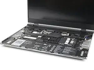
Use this guide to remove and replace the antennas in your Framework Laptop 16.

  1. FyZqYQXlGGSUVdfO
    • Unplug all cables and fully shut down your laptop.

  2. KX6SbVDOSK11tpww
    KX6SbVDOSK11tpww
    xUsiPWFWSHywwlyH
    YUTaVvGIQMvEBoVL
    • Use your fingernail to pull out the two Input Module latches and unlock them.

    • The latch will show red if it's unlocked.

  3. SJk2GqymsGfFPtk6
    SJk2GqymsGfFPtk6
    qYPAIGK4ZAN1UcxK
    RJPENmljQ6MIcvnN
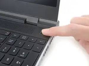
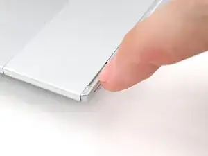
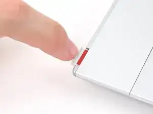
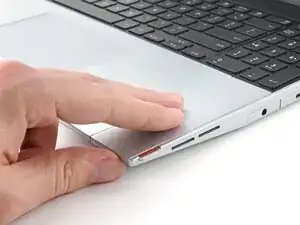
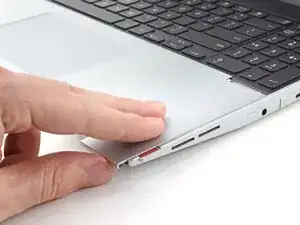
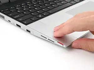
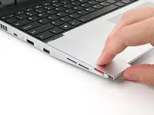
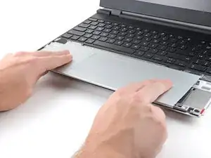
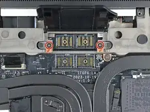
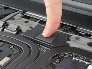
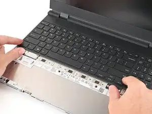
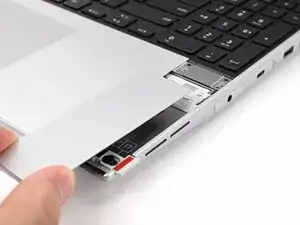
    • Use your fingers to slide the Touchpad Spacer toward the bottom edge of the laptop and unclip it.

    • If you're having trouble, check if the corresponding Input Module latch is properly unlocked.

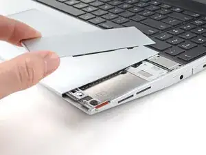
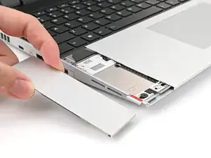
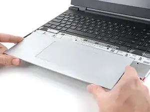
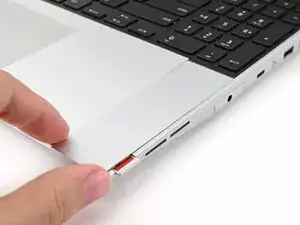
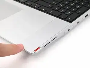
    • Lift the Touchpad Spacer off the laptop and remove it.

  4. jNWbnEQoPE1b5FNs
    jNWbnEQoPE1b5FNs
    T4eCedmNWxtIK3E4
    qMrYphKZARGoeODv
    • Repeat the same procedure for the other touchpad spacer.

  5. yYIvnKNYAZ5ZR5Cw
    yYIvnKNYAZ5ZR5Cw
    1OO4eJ2caggITR13
    fbmNJeKVP62XPULp
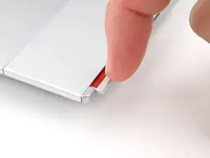
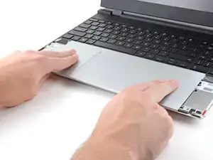
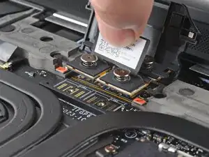
    • Use your fingers to slide the Touchpad Module toward the bottom edge of the laptop and disconnect it.

    • If you're having trouble, check if the Input Module latches are properly unlocked.

    • Lift the Touchpad Module and remove it.

  6. WXjcPFl2MgDiX2PZ
    WXjcPFl2MgDiX2PZ
    PojU1s2ZQqyfYBvO
    YlWkflmfJPHDuZov
    • The keyboard is held in place with strong magnets. Apply gradually increasing force to avoid having the keyboard violently eject.

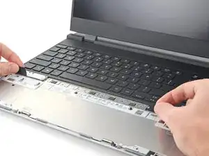
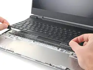
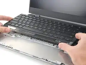
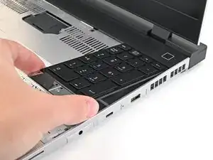
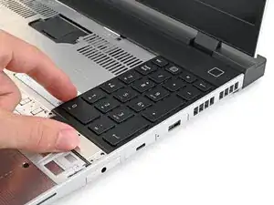
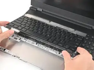
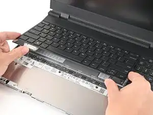
    • Grip the two pull tabs along the bottom of the keyboard and lift until its magnets release.

    • Remove the keyboard.

  7. hesMM66MFJtTfvCZ
    hesMM66MFJtTfvCZ
    3ZJ4rrrJTvR22eiV
    WesxvpHZwQSNZ3fK
    • Your Input Module(s) might be different, but the procedure to remove them is the same.

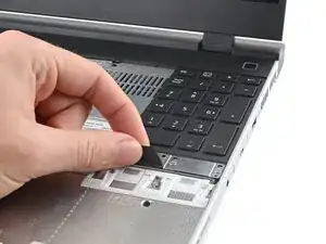
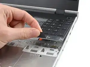
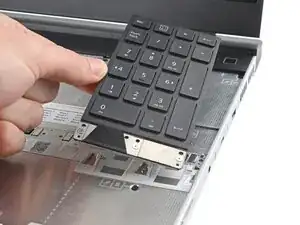
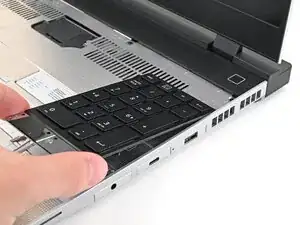
    • Grip the pull tab at the bottom of the Input Module and lift until its magnets release.

    • Remove the Input Module.

    • Repeat for any remaining Input Modules.

  8. SRhXtXWpl3DPYYAS
    SRhXtXWpl3DPYYAS
    55XONtqi1PZJQADv
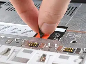
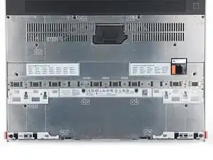
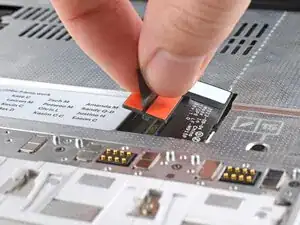
    • Grip the black pull tab on the Mid Plate cable press connector.

    • Lift up to disconnect the Mid Plate cable.

  9. aJoO4s4sLmUA5SSt
    aJoO4s4sLmUA5SSt
    EkZ2H5vKL2LW6Els
    • The Mid Plate screws are ordered from 2–17 (number 1 is the press connector). You don't have to follow the order, but you can use it to help keep track of the screws you've loosened.

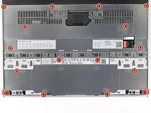
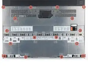
    • Use your Framework Screwdriver to loosen the 16 captive T5 Torx screws securing the Mid Plate.

  10. VFMpNOrkg5EiKwlo
    VFMpNOrkg5EiKwlo
    VMfwxIagCZvb511j
    ZQ1ZDWKwVKQrjDYL
    • Use your fingers to lift the Mid Plate off the laptop and remove it.

  11. lRVXxLICEGdocSrI
    lRVXxLICEGdocSrI
    JCgtidXYDtu1PaVO
    • Lift the interposer door by its black pull tab and let it rest upright.

  12. QUSO5HwTLuMIAlVF
    QUSO5HwTLuMIAlVF
    UqPaLZBxyUeWB3Xm
    • If you have the Graphics Module installed, your interposer will have four screws. If you have the Expansion Bay Shell installed, you'll have three screws instead.

    • If you have the Graphics Module, use your Framework Screwdriver to loosen the four captive T5 Torx screws securing the interposer.

    • If you have the Expansion Bay Shell, use your Framework Screwdriver to loosen the three captive T5 Torx screws securing the interposer.

  13. RRTnHiOVf2SmbBIL
    RRTnHiOVf2SmbBIL
    Xd5pXwSgLBOLaLnx
    • Lift the interposer by its pull tab and remove it.

  14. vDRVlx6RISCSiUcm
    vDRVlx6RISCSiUcm
    nrTLBFYiR4YNSALf
    dLPk65iSypbKMwLt
    • Use your Framework Screwdriver to loosen the two captive T5 Torx screws securing the module in the Expansion Bay.

    • Close the interposer door before continuing.

  15. EV6hxOxWhSeLhJgx
    EV6hxOxWhSeLhJgx
    OvgJqGPQnSC15AdL
    wQBqnhWGprulkl1l
    • Close your laptop and flip it over.

    • Slide the Expansion Bay Module out of the laptop and remove it.

    • The module should slide out easily. If you feel any resistance, check if the screws holding it in place are fully loosened.

    • Flip your laptop and reopen it.

  16. MBIEZmQ4ohlCsjYA
    MBIEZmQ4ohlCsjYA
    BwFJOVuiGGKCDS5x
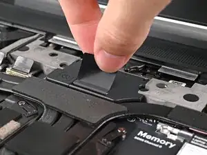
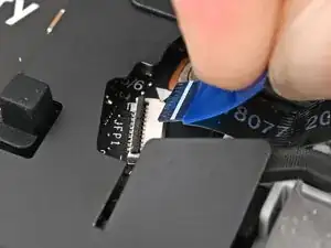
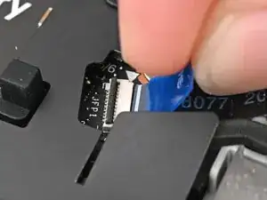
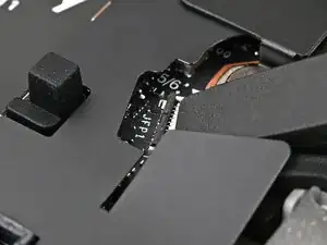
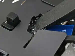
    • Use the flat end of your Framework Screwdriver, or a clean fingernail, to lift up the locking tab on the fingerprint reader ZIF connector next to the memory.

  17. FBMuVHkomoZUpPH1
    FBMuVHkomoZUpPH1
    oA3hLlmRmdfb1PwC
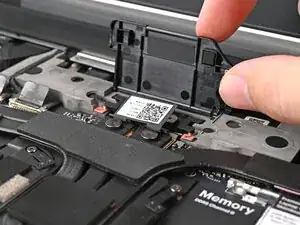
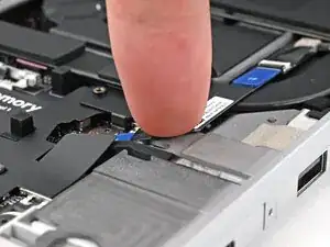
    • Use your fingers to grip the blue pull tab and slide the fingerprint reader cable straight out of its socket.

  18. nowIhewWYuAZsuLu
    nowIhewWYuAZsuLu
    KgMLYOAU4q4335DG
    YUb1K4hcBP1DskVV
    • The fingerprint reader cable is lightly adhered to the laptop's frame.

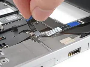
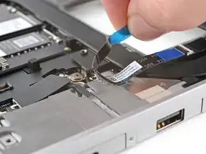
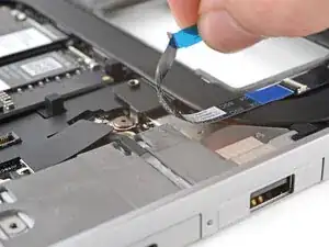
    • Use your fingers to peel the fingerprint reader cable away from the frame and separate the adhesive.

  19. 6VCdAUGj2cWHTdXf
    6VCdAUGj2cWHTdXf
    lFHDp6VISWM6ZWjE
    1jCaqMk5c5uFaCrb
    • The ventilation plate is held in place with magnets.

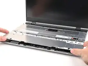
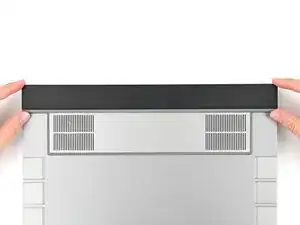
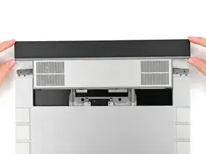
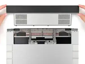
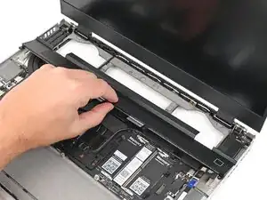
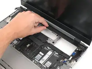
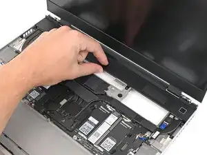
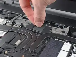
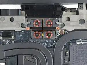
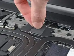
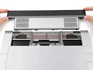
    • Lift the bottom of the ventilation plate and pull it away from the laptop until the magnets release.

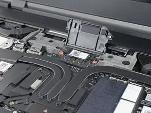
    • Remove the ventilation plate.

  20. ZraR5hRvK1scuQ4B
    ZraR5hRvK1scuQ4B
    dpaOY2OTDQYHKn1t
    • Use your Framework Screwdriver to loosen the captive T5 Torx screw securing Wi-Fi module.

    • The module might pop up at a shallow angle when you loosen the screw.

  21. kxIs2q2AfRQJYZ3I
    kxIs2q2AfRQJYZ3I
    5fwEQhuQLLkCoV41
    • Slide the clear plastic cover straight off the module and remove it.

  22. diSvMbLLmRckW4OX
    diSvMbLLmRckW4OX
    jmfJKrH1QpdZqbAo
    K1bfeUb4AS1uM5WM
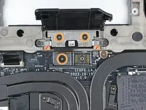
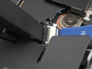
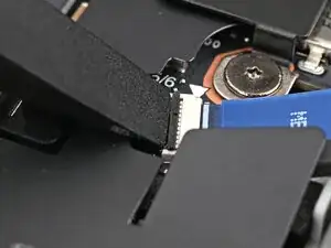
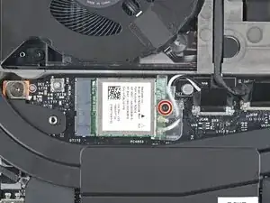
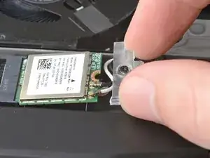
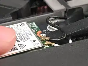
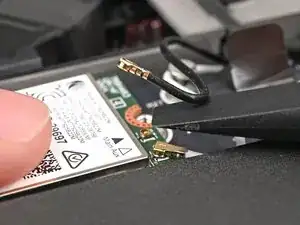
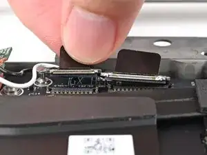
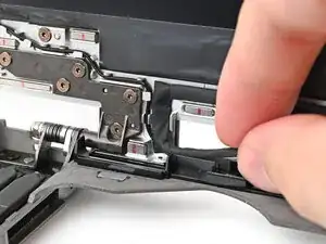
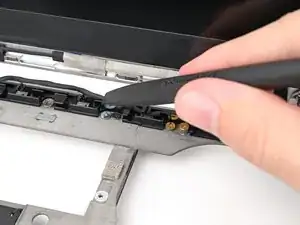
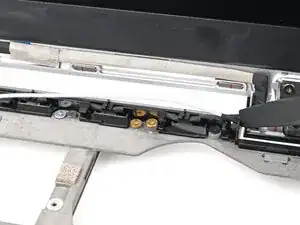
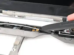
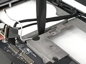
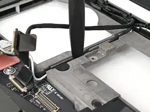
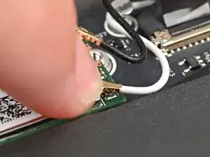
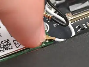
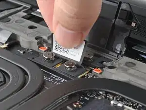
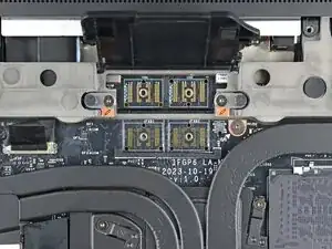
    • While holding the Wi-Fi module down, insert the flat end of your Framework Screwdriver one of the coaxial connectors, where the cable meets the metal head.

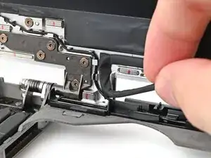
    • Lift the screwdriver straight up to disconnect the coaxial cable.

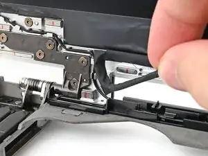
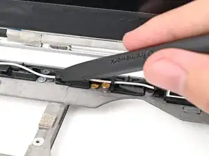
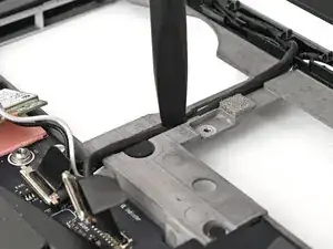
    • Repeat for the other coaxial cable.

  23. tgbiD2fxhTAZk5iO
    tgbiD2fxhTAZk5iO
    dc4IkrBY5APGZOf4
    y56IctmrjLDBTV5I
    • The bezel is secured with magnets.

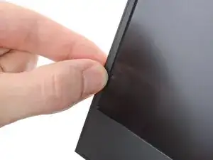
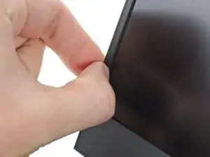
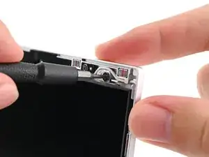
    • Slide your fingernail under the inside edge of either bottom corner of the bezel.

    • Pull the bezel away from the screen to release the first few magnets.

  24. sr4LPHw3fQ1daSgx
    sr4LPHw3fQ1daSgx
    ixNnblugO1i6VZDu
    JLaLQs4ucMVhaMHp
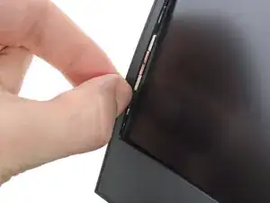
    • Lift the bezel around the perimeter of the screen until all of its magnets are released.

    • Remove the bezel.

  25. fdlX1ZigVAEoTtJt
    fdlX1ZigVAEoTtJt
    bMt3JwDXMQKXFvoH
    Sd5AevEchhM122ej
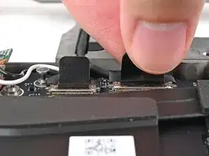
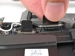
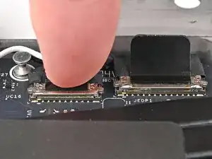
    • Grip the eDP cable connector to the right of the Wi-Fi module slot by its pull tab and lift up to disconnect it.

    • Repeat for the webcam cable connector next to it.

  26. 4CI31RNiq5UPhJ2I
    4CI31RNiq5UPhJ2I
    tgHYDnDpIjMaTuZJ
    gY2IYrxAUaQX2VjJ
    • Lift the eDP, webcam, and antenna cables out of their vertical slot in the Bottom Cover.

  27. 1LRpASjNLJNKBHLt
    1LRpASjNLJNKBHLt
    Brl2GiOdNXWuYSM2
    CeSvRc3u6QhgBXAb
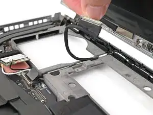
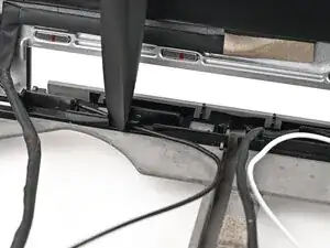
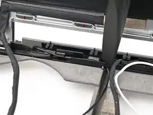
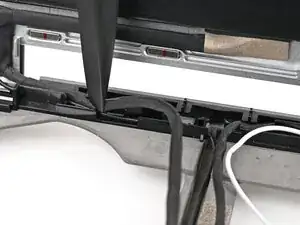
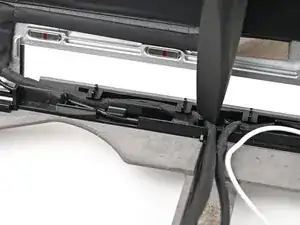
    • Use your fingers to guide the eDP cable out of its clips along the top left edge of the Bottom Cover.

  28. 2qa5NBgvvcRMqWdn
    2qa5NBgvvcRMqWdn
    L2pmuoBhiGquKMtR
    ILIIIFlSDc2OpdnQ
    • Repeat the previous step for the black antenna cable.

  29. 2tCVOQrOyURhZWoI
    2tCVOQrOyURhZWoI
    hGWVYxct1sFbeIg4
    gCHk1S5BIErHQcV1
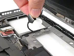
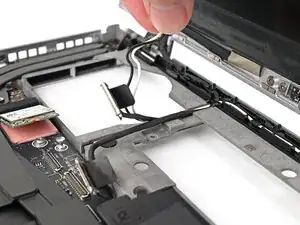
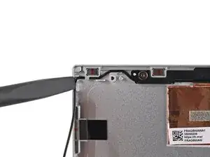
    • Use your fingers to guide the white antenna cable out of its clips along the top right edge of the Bottom Cover.

  30. XK5Tc4sbpl51ZcfE
    XK5Tc4sbpl51ZcfE
    KcjtqMVKPYnZHrQ2
    tGHeI6CPEYfJgiAP
    • Repeat the previous step for the webcam cable.

  31. BBvqrS25GKRUa1nD
    BBvqrS25GKRUa1nD
    52EBq4KArfx6qKxO
    26WgWA5UvM4obE1I
    • The eDP cable is lightly adhered to the Top Cover at its "bend" near the bottom left corner.

    • Grip the eDP cable near its bend and peel it off the Top Cover.

  32. MmWq5FrdeBAQPOQl
    MmWq5FrdeBAQPOQl
    jY2swWX5VIWp35FS
    PFu5Vn4Ffbqn4oW6
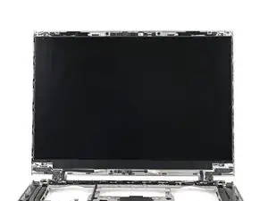
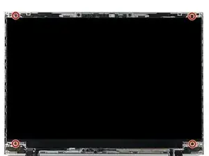
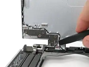
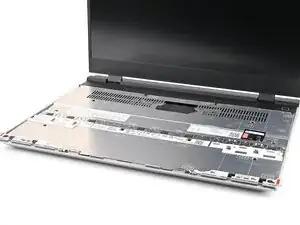
    • While supporting the display with one hand, use your Framework Screwdriver to remove the four 2.4 mm‑long T5 Torx screws securing the display.

  33. el6ZLXBhPrIPCfyP
    el6ZLXBhPrIPCfyP
    OntZNQUyOUJCVruL
    AS46OrJ3yVEbEAyJ
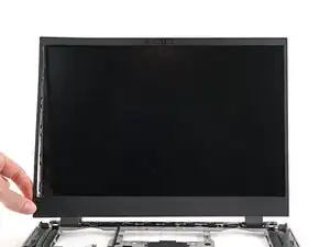
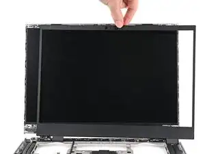
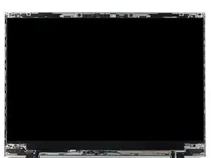
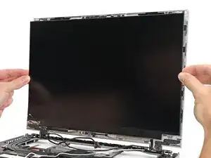
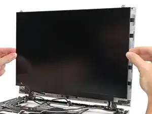
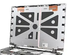
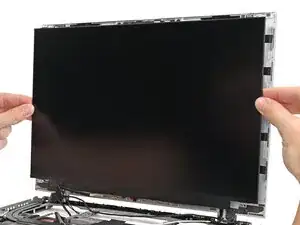
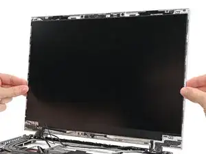
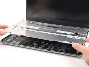
    • Grab the display and pull it straight off the Top Cover to free it from its alignment pegs.

    • Remove the display.

  34. ndTEZLqiTEZAOSoe
    ndTEZLqiTEZAOSoe
    JgZogk4SU1HJZDbH
    sKQYrNYQKPwJ6Gn3
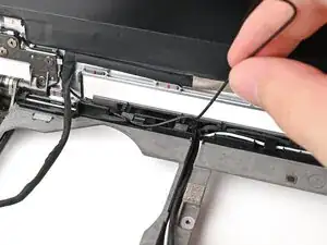
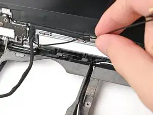
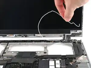
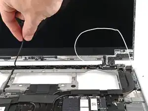
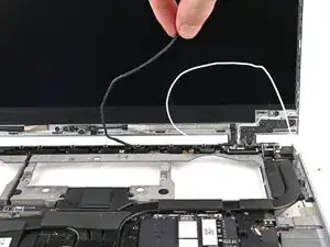
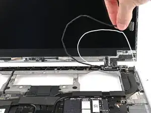
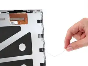
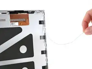
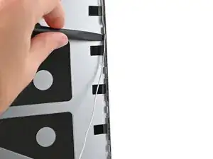
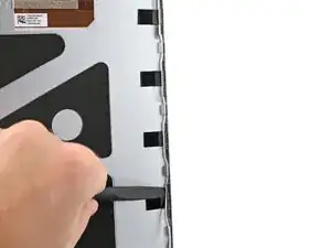
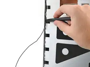
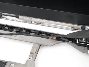
    • Use your fingers to guide the black antenna cable out of its clips on the bottom left corner of the Top Cover.

  35. YQwmYDuZbSViLMhK
    YQwmYDuZbSViLMhK
    ik2UFspPRisJ6bCl
    2GuMAjpYEEHvITB2
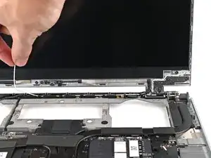
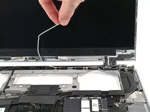
    • Repeat the previous step for the clips along the left edge of the Top Cover until the cable is completely free.

  36. bYswnRWiHMfHPpXD
    bYswnRWiHMfHPpXD
    6MAxHUqIRJJsvFic
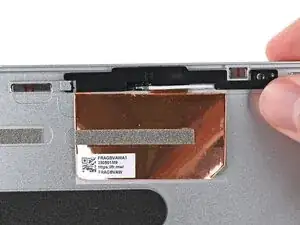
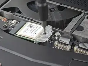
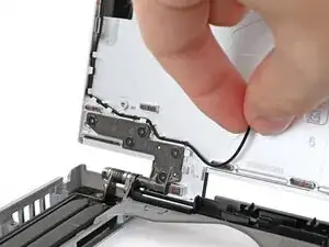
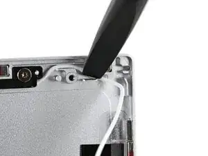
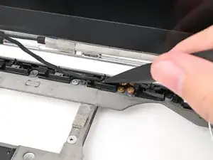
    • Use your Framework Screwdriver to remove the 2.4 mm‑long T5 Torx screw securing the left antenna.

  37. OADq4PO1YyHRXBvb
    OADq4PO1YyHRXBvb
    HYVsNxvyWvKKjLZV
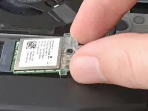
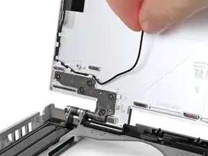
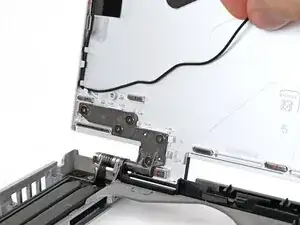
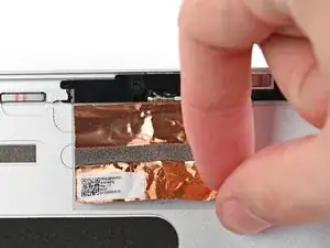
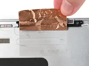
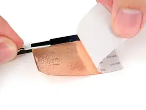
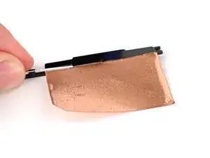
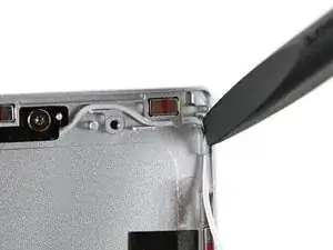
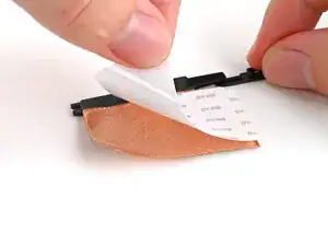
    • Use the flat end of your Framework Screwdriver to peel up a corner of the left antenna's copper film until you can grip it with your fingers.

  38. TB12WaOqDQkwpUKv
    TB12WaOqDQkwpUKv
    TMbGrlGNtUUewt45
    • Use your fingers to peel the copper film off the Top Cover.

  39. TwDoQGuaWPrnGnHb
    TwDoQGuaWPrnGnHb
    jJk4LxZhXHSdXxPG
  40. SN2jrh4C6pXTF5Qn
    SN2jrh4C6pXTF5Qn
    mJI2RstJG5EVr6Pn
    gTBgrj6UOVnvN2nD
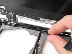
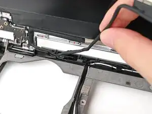
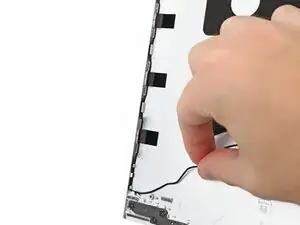
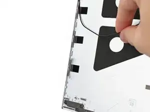
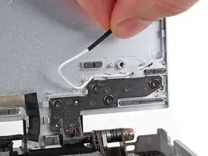
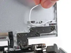
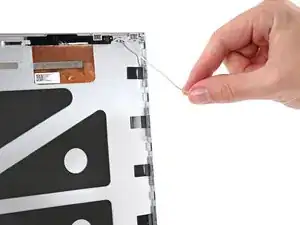
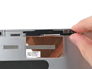
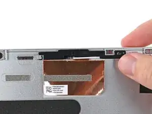
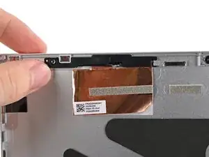
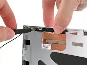
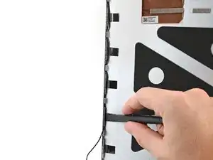
    • Use your fingers to guide the white antenna cable out of its clips on the bottom right corner of the Top Cover.

  41. shJPbXFEFsI4UL24
    shJPbXFEFsI4UL24
    OPfBRd53gBAWGwbD
    2MMZjFQSnG2aFhZS
    • Repeat the previous step for the clips along the right edge of the Top Cover until the cable is completely free.

  42. pdbHx3ETOKu6jPaK
    pdbHx3ETOKu6jPaK
    YwfbdJMEZXHTO5Ma
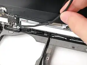
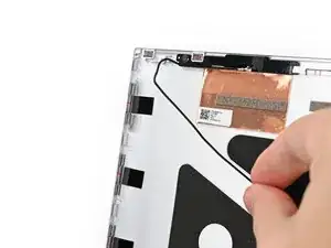
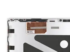
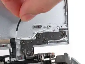
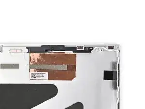
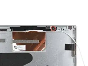
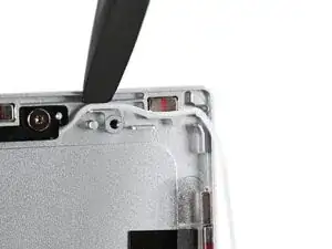
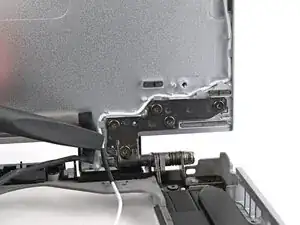
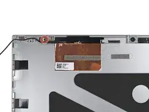
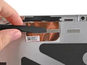
    • Use your Framework Screwdriver to remove the 2.4 mm‑long T5 Torx screw securing the right antenna.

  43. QPVHxhytNFKaMPM6
    QPVHxhytNFKaMPM6
    IX2ZNtQlYEOhQsBX
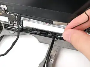
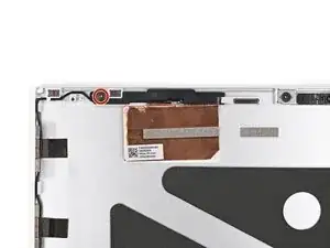
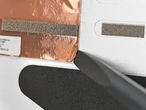
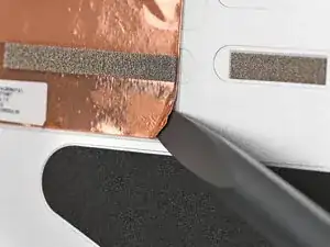
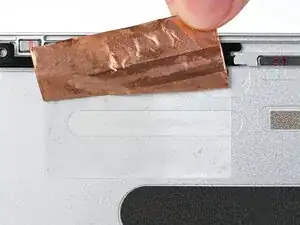
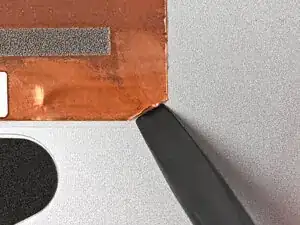
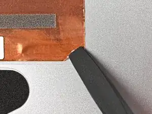
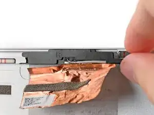
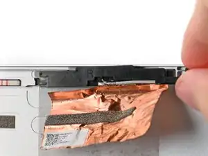
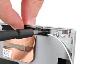
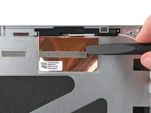
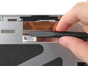
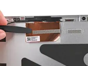
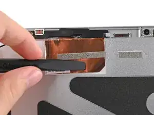
    • Use the flat end of your Framework Screwdriver to peel up a corner of the right antenna's copper film until you can grip it with your fingers.

  44. CxstLJeutAwXNbHQ
    CxstLJeutAwXNbHQ
    rZAsCYeXXYGmjdBN
    • Use your fingers to peel the copper film off the Top Cover.

  45. JmFNkhOaPUwGyqfk
    JmFNkhOaPUwGyqfk
    BOUGIc31oFsVXYPS
  46. yAqjOcYW4FxBfQJa
    • Congratulations on completing disassembly! The remaining steps will show how to reassemble your Framework Laptop.

  47. YpJXNFMJENuFDkdt
    YpJXNFMJENuFDkdt
    VLgZXYsbCrM1fE3p
    • Remove the liner from the back of your replacement right antenna.

    • The right antenna has a white cable and has an R printed on its front.

  48. qgAA2FHCvpNLDNNh
    qgAA2FHCvpNLDNNh
    sLwvE3Ict1mZGdbB
    puAxBkBLQQXfhRop
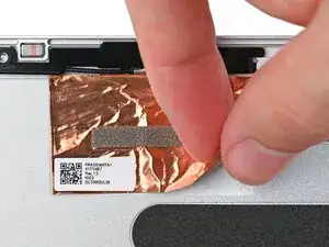
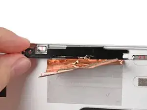
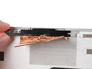
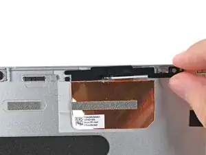
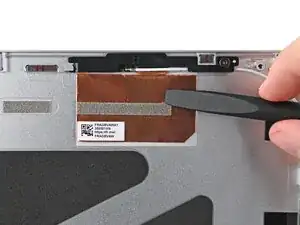
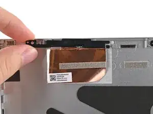
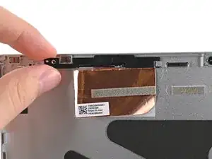
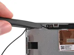
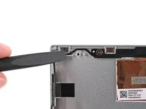
    • Use your fingers to slide the right antenna into its slot on the Top Cover and press it into its alignment peg.

  49. BTqvByjnmyu5HgQS
    BTqvByjnmyu5HgQS
    BIjmD1aUySQ12AYV
    • While keeping the antenna pressed into place, use your Framework Screwdriver to install the 2.4 mm‑long T5 Torx screw securing the right antenna.

  50. PqHlqdRZupO2cAHX
    PqHlqdRZupO2cAHX
    juXwoCaHdblXGyi4
    pPTXSpUWySYZfADR
    • Use the flat end of your Framework Screwdriver to press the copper film onto the Top Cover and adhere it.

  51. ycHDI61hANsHUbXk
    ycHDI61hANsHUbXk
    HtTLYNKhEASPggtD
    IZG4nQHdXeVmhtAR
    • Use the flat end of your Framework Screwdriver, or your fingers, to press the white antenna cable into its clips at the top right corner of the Top Cover.

  52. b1JrrHLLYyrrta5g
    b1JrrHLLYyrrta5g
    giwrmj6pMPK3E62M
    HF6DLhcbqp44qgFR
    • Repeat the previous step for the clips along the right edge of the Top Cover.

  53. VhHQrqWtkoAmYJOL
    VhHQrqWtkoAmYJOL
    XkaCLZbbfc2I14vQ
    • Remove the liner from the back of your replacement left antenna.

    • The left antenna has a black cable and has an L printed on its front.

  54. ZF2kvUtVTKx5jXOI
    ZF2kvUtVTKx5jXOI
    CHWSxN4JAySOoElN
    JdSZbUZEuwSZcGyr
    • Use your fingers to slide the left antenna into its slot on the Top Cover and press it into its alignment peg.

  55. IO6SalJDSeOhICGR
    IO6SalJDSeOhICGR
    Sfk6GLuciO2aFrbM
    • While keeping the antenna pressed into place, use your Framework Screwdriver to install the 2.4 mm‑long T5 Torx screw securing the left antenna.

  56. CYFTShKLYuyDMoQf
    CYFTShKLYuyDMoQf
    EQPkFtckZdpoiddR
    FiSKhmYbq1x62ZhL
    • Use the flat end of your Framework Screwdriver to press the copper film onto the Top Cover and adhere it.

  57. IRxJnyeWqUwWaPfI
    IRxJnyeWqUwWaPfI
    ryFOcixMjwo1B22t
    LTMnMNSVGtMj4TKT
    • Use the flat end of your Framework Screwdriver, or your fingers, to press the black antenna cable into its clips at the top left corner of the Top Cover.

  58. boIRAUHqXHU6jjCg
    boIRAUHqXHU6jjCg
    pKyYaDvErLPkHmpw
    2L1CbsFyGQu6ArjQ
    • Repeat the previous step for the clips along the left edge of the Top Cover.

  59. nCdgymAUHOxW4aQH
    nCdgymAUHOxW4aQH
    CtYWQDQnNZIsviAs
    • Align the display with its alignment pegs and place it on the Top Cover.

  60. MmWq5FrdeBAQPOQl
    MmWq5FrdeBAQPOQl
    jY2swWX5VIWp35FS
    PFu5Vn4Ffbqn4oW6
    • While supporting the display with one hand, use your Framework Screwdriver to install the four 2.4 mm‑long T5 Torx screws securing the display.

  61. 26WgWA5UvM4obE1I
    26WgWA5UvM4obE1I
    52EBq4KArfx6qKxO
    • Press the bend in the eDP cable onto the Top Cover to re‑adhere it.

  62. grA52eURD4nX4AlI
    grA52eURD4nX4AlI
    pGY1AAgfEmBKSR5X
    Bmaik2RmCtkLKcue
    • Use the flat end of your Framework Screwdriver, or your fingers, to press the webcam cable into its clips at the top right edge of the Bottom Cover.

  63. Oq3OgOWlQprJ1ujI
    Oq3OgOWlQprJ1ujI
    4hjbEXsHBwQq5Qlt
    qgpQZmREX5sRhK3r
    • Repeat the previous step for the white antenna cable.

  64. pXumJMFLoZP4BCQE
    pXumJMFLoZP4BCQE
    VTVJ6DXTsqNKWGQU
    • Use the flat end of your Framework Screwdriver, or your fingers, to press the black antenna cable into its clips at the top left edge of the Bottom Cover.

  65. qdMmkd4uCKcPbonS
    qdMmkd4uCKcPbonS
    GQLP1yvdKmjHoEAm
    • Repeat the previous step for the eDP cable.

  66. OvCZQaNS3I6Isigq
    OvCZQaNS3I6Isigq
    IFIwQwEURqIclWv4
    uDLSZBIXbDMxmNnf
    • Press the eDP, webcam, and antenna cables into their vertical slot in the Bottom Cover.

  67. PASbcq4hiZyMF5Kb
    PASbcq4hiZyMF5Kb
    UTfZZdS1Qh3ORMit
    • Press the eDP and webcam cable connectors straight down into their sockets to connect them.

  68. ixNnblugO1i6VZDu
    ixNnblugO1i6VZDu
    sr4LPHw3fQ1daSgx
    • Align the bezel over the perimeter of the display and let the magnets pull the bezel into place.

    • The bezel should "snap" into place. If it doesn't, realign it and make sure it sits flush with the display.

  69. BjSCTpMMJxYTWOO1
    BjSCTpMMJxYTWOO1
    Q6rcMEQ1uTWO6enf
    wWi4aYhE6lWWdR6D
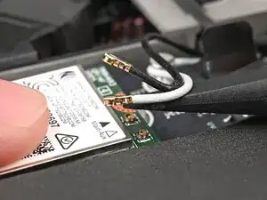
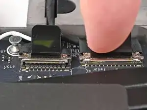
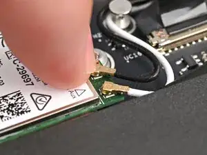
    • Hold the Wi-Fi module down with your finger.

    • Position the white antenna cable connector over the left Wi-Fi module's coaxial socket.

    • If you're unsure which cable goes where, refer to the arrows on the Wi-Fi module for which color cable matches with its connector.

    • Tweezers can help position the connector.

    • Use your finger to press the connector into place. You should feel a faint click, and the cable will stay attached to the socket by itself.

    • These connectors are very delicate! If the connector doesn't feel like it's clicking in place, reposition the connector and try again.

    • Repeat the procedure with the black antenna cable.

  70. 5fwEQhuQLLkCoV41
    5fwEQhuQLLkCoV41
    kxIs2q2AfRQJYZ3I
    • Slide the clear plastic cover on the module and align its screw with the screw hole cutout.

  71. ZraR5hRvK1scuQ4B
    • Use your Framework Screwdriver to tighten the captive T5 Torx screw securing Wi-Fi module.

  72. J3irymcQVyspoqPB
    J3irymcQVyspoqPB
    vpxgM1U2oeJSnEv6
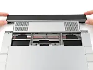
    • Lay the ventilation plate along the top edge of the laptop and let its magnets pull into place.

  73. gwEvWqFlhXauVOcq
    gwEvWqFlhXauVOcq
    xKFssJdsSsvPZGjR
    • Use your fingers to grip the blue pull tab and slide the fingerprint reader cable straight into its socket.

  74. YyhVDEW2sHFYkZPg
    YyhVDEW2sHFYkZPg
    F4kMTvJw6MoYEOGa
    • Use the flat end of your Framework Screwdriver, or a clean fingernail, to press down the locking tab on the fingerprint reader ZIF connector.

  75. hqoukOlBlYcSXgNJ
    • Press the fingerprint reader cable to the frame to re-adhere it.

  76. YPDWdpOxdFAqThNw
    YPDWdpOxdFAqThNw
    4WGwAwjGwkx5HfPL
    • Close the interposer door.

  77. 1uOUECOFI5DgNkT1
    1uOUECOFI5DgNkT1
    MDnfnN4Kbc3BVytc
    QIYI5bfaG4BABOMY
    • If you have the Graphics Module installed, your interposer will have four screws. If you have the Expansion Bay Shell installed, you'll have three screws instead.

    • If you have the Graphics Module, use your Framework Screwdriver to tighten the four captive T5 Torx screws securing the interposer.

    • If you have the Expansion Bay Shell, use your Framework Screwdriver to tighten the three captive T5 Torx screws securing the interposer.

    • Close the interposer door.

  78. XRFliQnLmIASWZoT
    XRFliQnLmIASWZoT
    4aKZ5YUfYYwMJnA3
    • Place the interposer over its spot between the Mainboard and the module.

    • Depending on if you're installing a Graphics Module or the Expansion Bay Shell, the interposer should be oriented so either rubber grommets or metal tabs cover the Expansion Bay screws.

  79. vDRVlx6RISCSiUcm
    vDRVlx6RISCSiUcm
    XN3g1sFD65EmNgXE
    • Use your Framework Screwdriver to tighten the two captive T5 Torx screws securing the Expansion Bay Module.

  80. fBJ2bmmBascXHxYK
    fBJ2bmmBascXHxYK
    bSDEVdYXNbEIByCp
  81. WNXCOLdJxWygeIlt
    WNXCOLdJxWygeIlt
    KDQ5biLCZamuGX4Z
    NtmyYbY1tlXxr6YA
    • Place the Mid Plate on the laptop, making sure it sits evenly on its alignment pegs.

  82. pqZIeK5rgaKTBWl4
    pqZIeK5rgaKTBWl4
    4spVx1SupfNvWdAX
    • Use your Framework Screwdriver to tighten the 16 captive T5 Torx screws in order (starting with 2) to secure the Mid Plate evenly.

  83. SHR1O2N1YLLv6ryr
    SHR1O2N1YLLv6ryr
    NTicb3BsOPOSLmwn
    • Align the Mid Plate cable press connector over its socket and press down to connect it.

  84. JyccFC2cavJAQkw2
    JyccFC2cavJAQkw2
    UBPFtlfVJwD5MG4C
    qDoJmL3yEaNiGyLv
    • Your Input Module(s) might be different, but the procedure to remove them is the same.

    • Align the top edge of the Input Module with the top edge of the laptop.

    • Lay the Input Module on the laptop and let the magnets pull the keyboard into place

    • Make sure the Input Module is seated properly on its alignment pegs and sits flush with the edges of the laptop.

    • Repeat for any remaining Input Modules.

  85. 2oPYqKStliPhyMNB
    2oPYqKStliPhyMNB
    Sa6jykktBZSuiFBK
    mSXYbDZf6nqTloeB
    • Align the top edge of the keyboard with the top edge of the laptop.

    • Lay the keyboard on the laptop and let the magnets pull the keyboard into place

    • Make sure the keyboard is seated properly on its alignment pegs and sits flush with the edges of the laptop.

  86. OGgC5a1tSqgNY2QF
    OGgC5a1tSqgNY2QF
    5m5NiQxMvTWjIbjQ
    • Place the Touchpad Module flat on its cutout so its clips are properly aligned.

    • Press the Touchpad Module down and slide it into place so it lines up evenly with the bottom edge of the laptop.

  87. nrQTspaoMXJKTnok
    nrQTspaoMXJKTnok
    rRqoTulPIcQVVcbP
    hH5fa2iJ4qxAPZjs
    • Place the Touchpad Spacer over its spot on the laptop with the bottom edge overhanging slightly.

    • Slide the Touchpad Spacer towards the top of the laptop to secure it.

    • Repeat the same procedure for the other Touchpad Spacer.

Conclusão

You finished fixing your Framework Laptop!

Take your e-waste to an R2 or e-Stewards certified recycler.

If you need help, contact Framework support.

Alex Diaz-Kokaisl

Membro desde: 16/01/22

227430 Reputação

0 comentários