Introdução
-
-
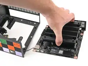
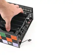
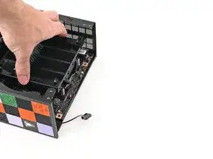
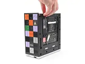
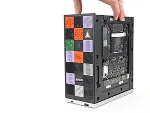
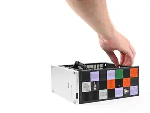
Grab the Mainboard by its heatsink and slide it into the chassis.
-
Align the rear ports with its cutout and the screw posts with the screw holes on the Mainboard.
-
Make sure no cables are trapped underneath the Mainboard before continuing.
-
-
-
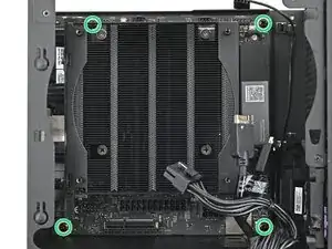
Use your Framework Desktop Screwdriver to install the four 8.2 mm‑long Phillips screws securing the Mainboard.
-
-
-
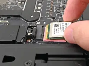
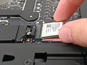
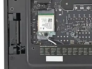
Align the Wi-Fi module's gold contacts and notch with the socket on the Mainboard.
-
Insert the Wi-Fi module into the socket at a shallow angle. The gold contacts should mostly be covered by the socket.
-
-
-
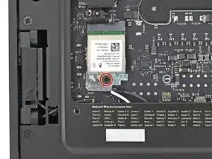
Use your Framework Desktop Screwdriver to install the 7.0 mm‑long Phillips screw securing the Wi-Fi module.
-
-
-
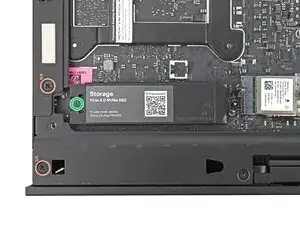
Use your Framework Desktop Screwdriver to loosen the captive T5 Torx screw securing the heat spreader.
-
-
-
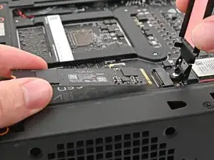
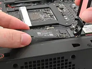
While holding the SSD heat spreader upright, align the SSD's gold contacts with its socket.
-
Insert the SSD into the socket at a shallow angle. The gold contacts should mostly be covered by the socket.
-
Lay the heat spreader back onto the SSD.
-
-
-
Use your Framework Desktop Screwdriver to tighten the captive T5 Torx screw securing the SSD.
-
-
-
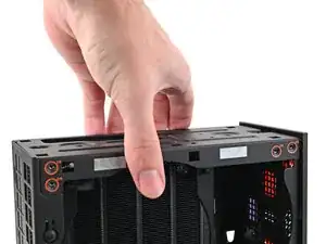
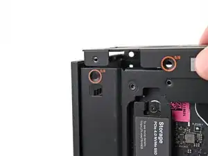
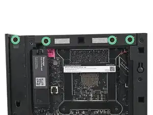
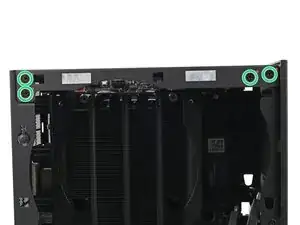
Place the top plate on top of the Desktop, making sure it slots into the chassis so the orange circles are visible.
-
-
-
Make sure the matching screw hole on the top plate labeled "5/8" is slotted on the inside of the Chassis so that the orange circle is visible.
-
-
-
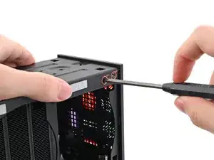
While holding the Desktop steady, use your Framework Desktop Screwdriver to install the eight 4.0 mm‑long Phillips screws securing the top plate.
-
-
-
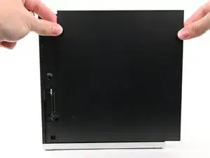
Slide the Right Panel onto the right edge of the chassis, from top to bottom, and press it flat to ensure its clips are slotted into place.
-
Push the Right Panel towards the base of the computer to engage the clips.
-
-
-
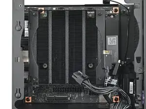
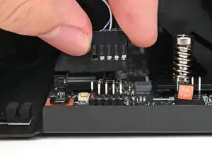
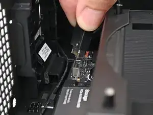
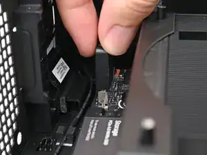
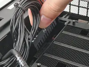
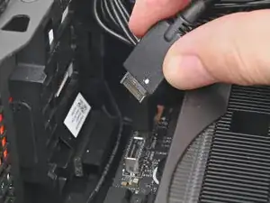
Orient the CPU power supply cable so its clip is facing the heatsink.
-
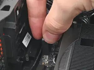
Slide the cable into its socket on the Mainboard until you feel it click into place.
-
-
-
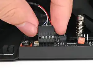
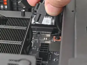
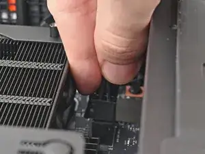
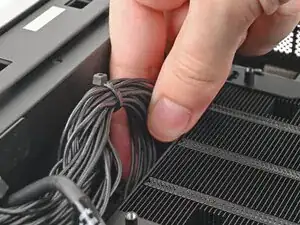
Orient the main power supply cable so its clip is facing away from the heatsink.
-
Slide the cable into its socket on the Mainboard until you feel it click into place.
-


To reassemble your device, follow these instructions in reverse order.