Introdução

Use this guide to remove and replace the antennas in your Framework Desktop.

  1. DjDhorNOQwh3ZGMT
    DjDhorNOQwh3ZGMT
    3HVtRyLTmEtZfvCu
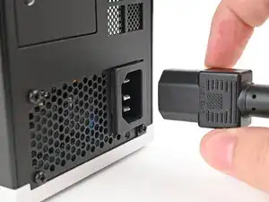
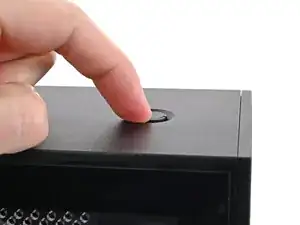
    • Before you begin repairs, shut down your Desktop from the operating system and unplug it.

    • Wait one minute before continuing to allow your Desktop to fully power down.

  2. bCnmRpDo2L1muYA5
    bCnmRpDo2L1muYA5
    PkjmE66QFWiGyJPD
    rXfwXpgdDlUm4VSA
    • If you installed the Handle on your Desktop, follow this step. Otherwise, skip it.

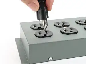
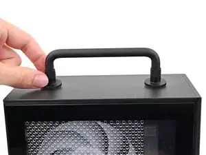
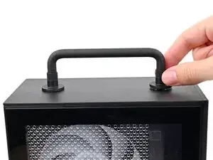
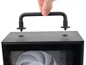
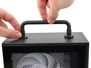
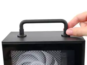
    • Rotate the Handle's screw threads counterclockwise on both sides until it comes free.

    • Remove the Handle.

  3. 25uSW5yTweC4DhJH
    25uSW5yTweC4DhJH
    NLSHNAcGIfXySxVC
    uIxWPNWJJEnVnIum
    • Use your finger to lift up the two D-rings on the Top Panel screws.

  4. BeKqSvRJr2nX2qFK
    BeKqSvRJr2nX2qFK
    odGLjCiIdEQeE2bh
    IDSwwb3LHUUaXukA
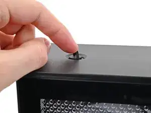
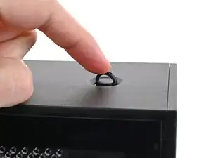
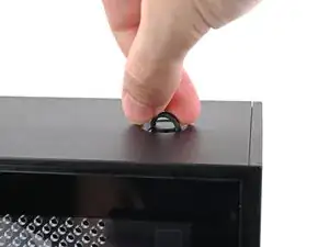
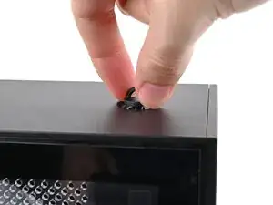
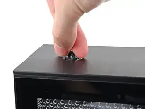
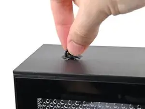
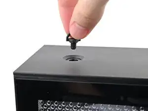
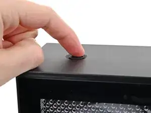
    • Use your fingers to twist the screw counter-clockwise and loosen it.

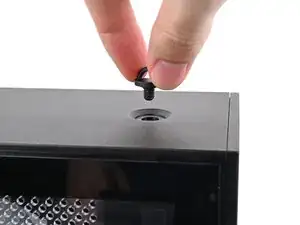
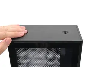
    • Remove the Top Panel screw.

  5. 4RopBQ6BtjnY1WrK
    4RopBQ6BtjnY1WrK
    ktjYiQLsGJUndqrb
    J4lBDyCSGfYoWxD4
    • Repeat the same procedure for the other Top Panel screw.

  6. jTMMgoIeaomUVn3V
    jTMMgoIeaomUVn3V
    k25EnLrWVNWIYJKF
    l1bqihYbxPsKZm41
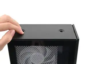
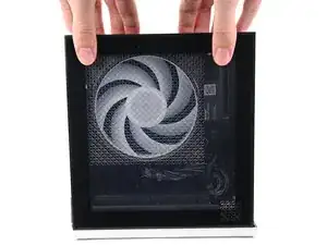
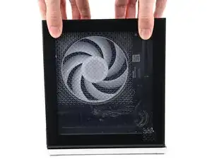
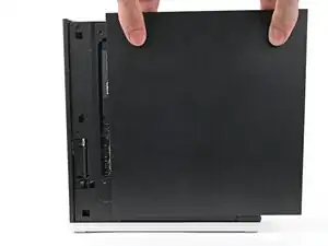
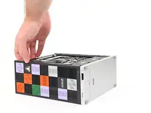
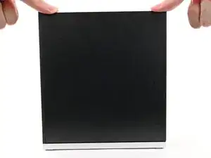
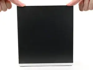
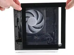
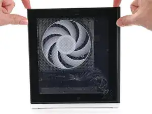
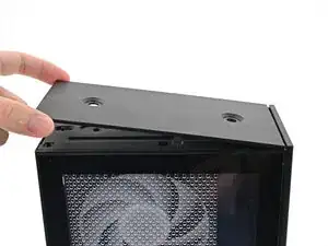
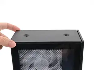
    • Slide the Top Panel towards the rear of the computer to release the clips securing it to the chassis.

    • If you're having a hard time gripping the Top Panel, use the screw holes to get a better handhold.

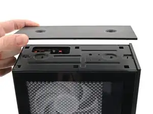
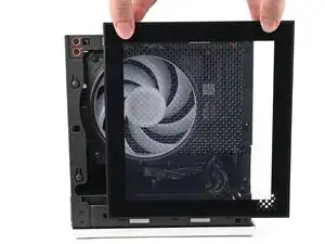
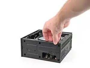
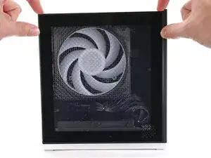
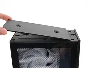
    • Lift the Top Panel off the chassis and remove it.

  7. XLTfeld1KUdjWOKV
    XLTfeld1KUdjWOKV
    W3VjNdQ4KsjDPN3e
    xqnJp46bmuCf5pno
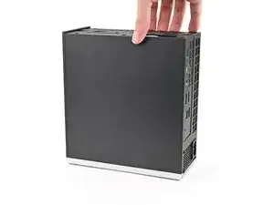
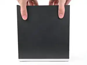
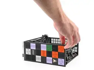
    • Use your fingers to grip the top of the Left Panel and slide it upward to release its clips.

    • Remove the Left Panel.

  8. ZHrFVeqRPOnJE6u4
    ZHrFVeqRPOnJE6u4
    oo5N5OPHpJCIAtUd
    • Lay down the Desktop on its side so the fan is facing upward.

  9. DsZB13WRF1jbbQMG
    DsZB13WRF1jbbQMG
    gK2SgLUMEhLPyDcS
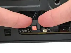
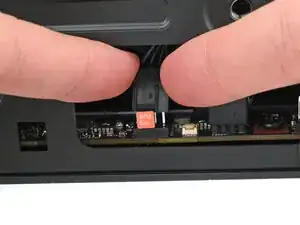
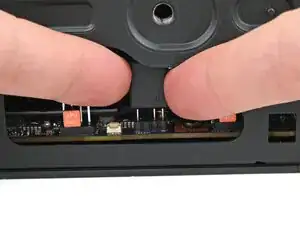
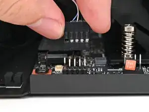
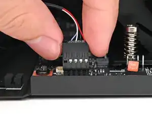
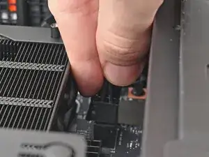
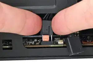
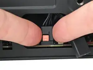
    • Use your fingers to lift the APU fan cable connector off its four‑pronged socket on the Mainboard.

  10. MtMUNuamBHYgkNWA
    MtMUNuamBHYgkNWA
    YhCfHtk6QNGEEKmY
    • If you aren't using an RGB fan, then skip this step.

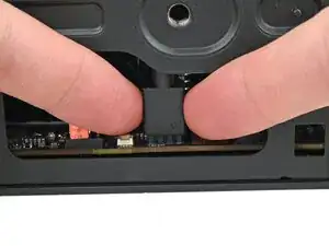
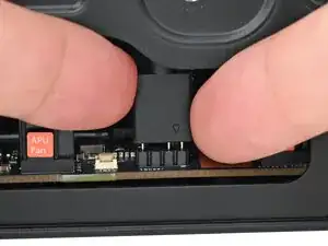
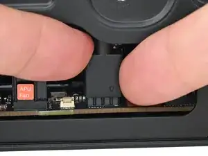
    • Use your fingers to lift the fan RGB cable connector off its three‑pronged socket on the Mainboard.

  11. wYCTGPWMAcOeR4XS
    wYCTGPWMAcOeR4XS
    SdYJJGSHmltiwLSx
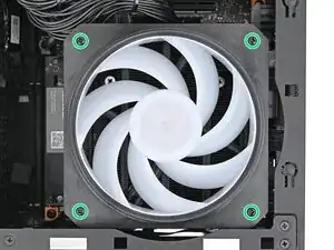
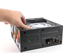
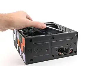
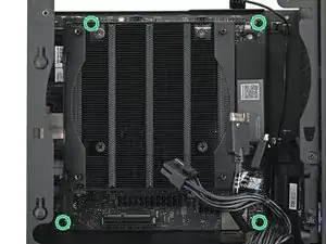
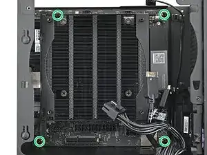
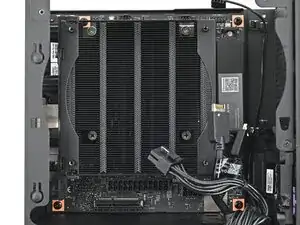
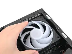
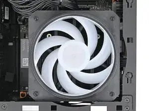
    • Use your Framework Desktop Screwdriver to remove the four 27.3 mm‑long Phillips screws securing the CPU fan and fan duct.

  12. a6lNGtOgVT5bSj4g
    a6lNGtOgVT5bSj4g
    ZLCCVV2aywoiGZSM
    • Lift the fan duct off the fan and remove it.

  13. CHxalKIsFQMXkPTS
    CHxalKIsFQMXkPTS
    ckmIUBoAtibQFaQj
    ZZ6j42hbHTrSJI1Y
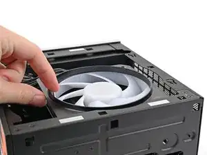
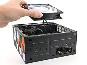
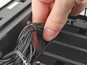
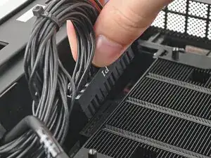
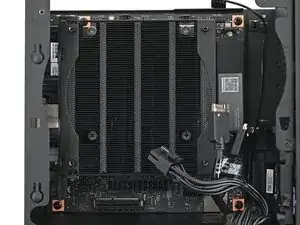
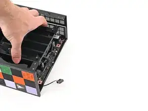
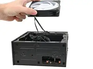
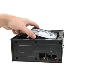
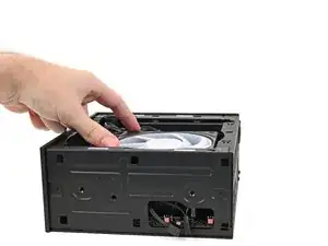
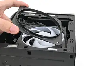
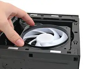
    • Lift the fan out of the chassis, making sure the cables thread through the side of the heatsink.

  14. IkKGZsIUwkmGw1fq
    IkKGZsIUwkmGw1fq
    RiY1w5f4QutkQZmS
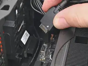
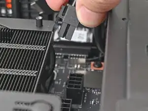
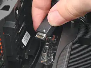
    • Pull the top Expansion Card connector straight out of its socket in the Mainboard to disconnect it.

  15. jDKtVhSVxSQIqPlA
    jDKtVhSVxSQIqPlA
    1GptQTd2QPkJOFCb
    • While squeezing the clip on the main power cable, pull it straight up and out of its socket to disconnect it.

  16. CPB6NlTZsjwca5RJ
    CPB6NlTZsjwca5RJ
    v1M2UQmutjdnMCDN
    • While squeezing the clip on the CPU power cable, pull it straight up and out of its socket to disconnect it.

  17. oMaoSoU5mLJYGOIG
    oMaoSoU5mLJYGOIG
    IsHaFZgRwDWInefi
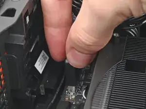
    • Pull the bottom Expansion Card connector straight out of its socket in the Mainboard to disconnect it.

  18. JyuRpCIYt5n21SEU
    JyuRpCIYt5n21SEU
    WNx4Y4v22eItDSaF
    • Lift the Desktop so it stands upright on your work surface.

  19. pWOAB2YbnIJVqwcb
    pWOAB2YbnIJVqwcb
    wbgDEFUWog6rZbRg
    36ksgPABSkJdVaFh
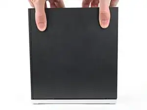
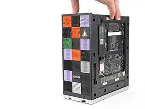
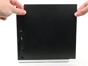
    • Use your fingers to grip the top of the Right Panel and slide it upward to release its clips.

    • Remove the Right Panel.

  20. PrMSMvP1u6Mldhvp
    PrMSMvP1u6Mldhvp
    FQo4GHGDCcDEYg6g
    OPHvQkt5DjEFKrDI
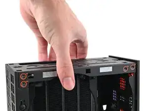
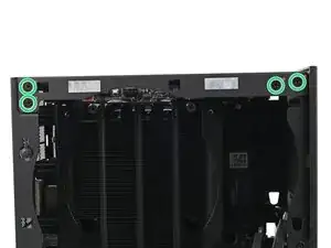
    • While holding the Desktop steady, use your Framework Desktop Screwdriver to remove the eight 4.0 mm‑long Phillips screws securing the top plate.

  21. k4DvEjHP23jFmvFa
    k4DvEjHP23jFmvFa
    OwJIJIPVTLfoOPGT
    • Lift the top plate off the Desktop and remove it.

  22. PeLKWCCQSDSRJAlW
    PeLKWCCQSDSRJAlW
    GbQesSQgRrMNghEW
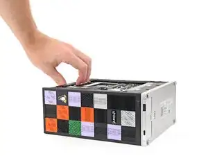
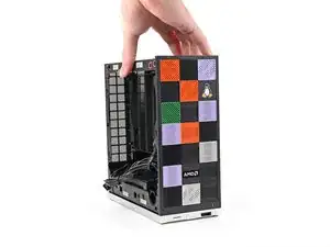
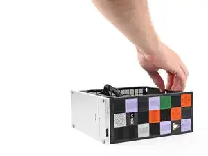
    • Lay the left side of the Desktop on your work surface so the underside of the Mainboard is facing upward.

  23. EgGBrYNZ2Ht3bq1q
    EgGBrYNZ2Ht3bq1q
    6fUqfEsGrVue1TaZ
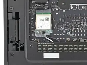
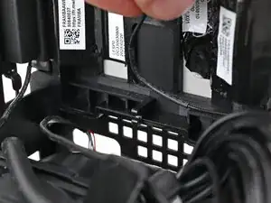
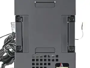
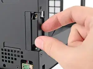
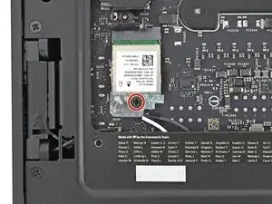
    • Use your Framework Desktop Screwdriver to remove the 7.0 mm‑long Phillips screw securing the Wi-Fi module.

  24. 6uXubkJo24QcdLqV
    6uXubkJo24QcdLqV
    DTXG6THAqDQ3BnRN
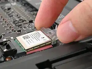
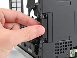
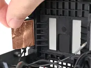
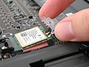
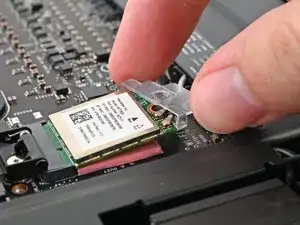
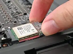
    • Use your fingers to slide the Wi-Fi module cover straight off the bottom of the module.

    • Remove the cover.

  25. wjNlESsFSMNgRaZr
    wjNlESsFSMNgRaZr
    BeIPgB1yTdQOM1w3
    QDGJKcsTHMFKMqBq
    • The Wi-Fi module has two delicate coaxial cable connectors. Follow this step carefully to avoid damaging them.

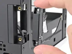
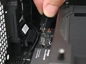
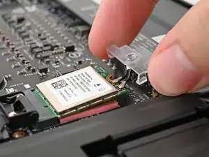
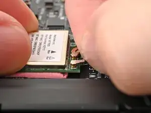
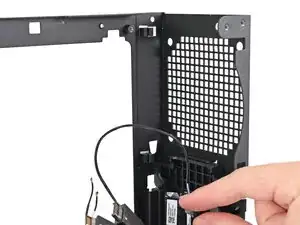
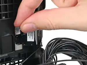
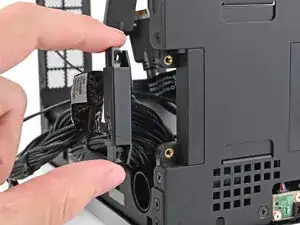
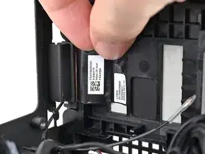
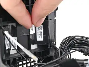
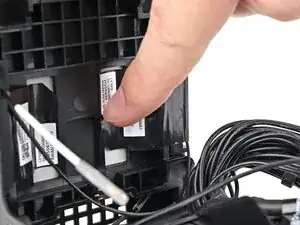
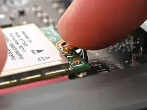
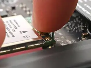
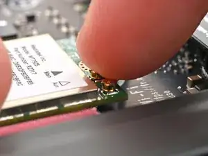
    • Press and hold the Wi-Fi module down with your fingers.

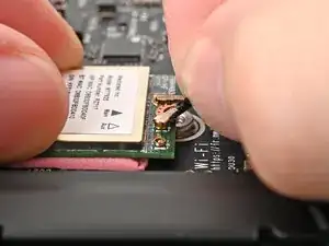
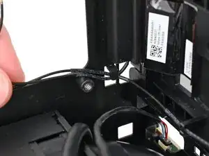
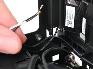
    • Use your fingers to grip the white antenna cable, as close to the metal head as possible.

    • If you have angled tweezers, slide one arm of a pair of tweezers under the antenna connector, as close to the metal head as possible.

    • Gently lift the connector straight up to disconnect the white antenna cable.

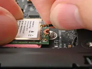
    • Repeat the procedure with the black antenna cable.

  26. m1UPSYW6mEZ5Maok
    m1UPSYW6mEZ5Maok
    26ErN6KvpjORhTTL
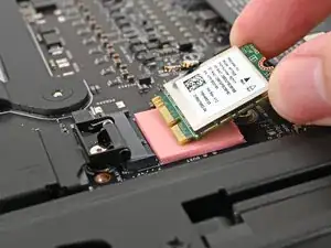
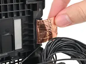
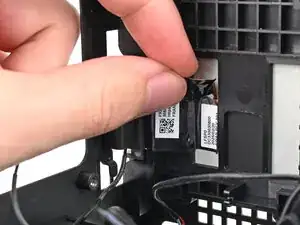
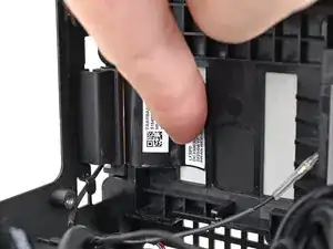
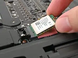
    • Grip the Wi-Fi module by its edges and pull it straight out of its socket.

    • Remove the Wi-Fi module.

  27. OXAaN5uJci2ZiCJw
    OXAaN5uJci2ZiCJw
    HLAodONJjvHWfybE
    • Rotate the Desktop onto its right side so the Mainboard is facing upward.

  28. KZ4cTVvtehE3GZsw
    KZ4cTVvtehE3GZsw
    fGHcmJYgb2YVvcha
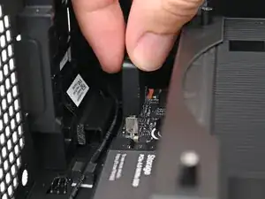
    • Use your fingers to lift the power button cable connector off its nine‑pronged socket on the Mainboard.

  29. xYETUKIPEOXWaIuF
    xYETUKIPEOXWaIuF
    mfaUgpwjtBWIdBFy
    • Use your Framework Desktop Screwdriver to remove the four 8.2 mm‑long Phillips screws securing the Mainboard.

  30. HWwoGkGkiLN5JeTB
    HWwoGkGkiLN5JeTB
    vLMlOYMIm1h4BRiP
    cjDjJkyfsRqUfhNM
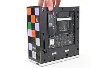
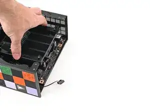
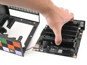
    • Grab the Mainboard by its heatsink and pull it towards the front of the Desktop to slide it out of the rear port cutout.

    • Only grab the heatsink by its left and right edges (the edges facing the back I/O ports and the Primary SSD). If you grab the other edges, you risk bending the heatsink fins.

    • Slide the Mainboard towards the top of the Desktop to remove it from the chassis.

  31. wEhLOXHCgwFoKyo3
    wEhLOXHCgwFoKyo3
    IHGvuALdL63e3s55
    IcYGDriQUKOPpRBY
    • Pull the power button cable out of its rubber clips on the chassis.

  32. I5i5XeQLqIDeEjY6
    I5i5XeQLqIDeEjY6
    ZKRDACFyvQOXlnIY
    • Push the antenna cables out of the metal hook in the chassis.

  33. 15lD2AjjvDbHpQ3F
    15lD2AjjvDbHpQ3F
    rWYRE4QONFphfYZs
    • Pull the black antenna cable out of the plastic clip in the chassis.

  34. kKfAvpYhCbvPBW5V
    kKfAvpYhCbvPBW5V
    OLnvYYoDOUuLVU6g
    • Use your fingers to peel the left antenna's copper film off the chassis.

  35. l33IEJVxUmn2upnF
    l33IEJVxUmn2upnF
    ACbyZlUV2NiXMmIF
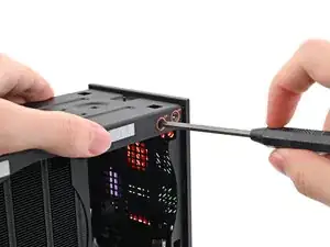
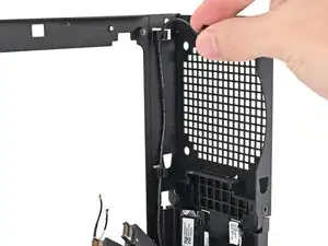
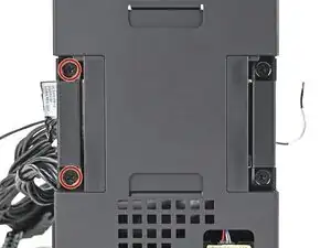
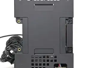
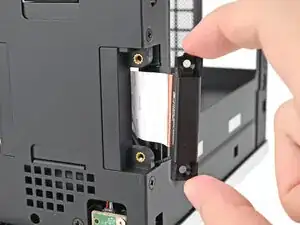
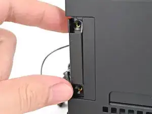
    • Use your Framework Desktop Screwdriver to remove the two 4.0 mm‑long Phillips screws securing the left antenna.

  36. flD2NPEuZv1CNGxS
    flD2NPEuZv1CNGxS
    ihrblKo3Wu6FSSLB
    • Lift the left antenna out of the chassis and remove it.

  37. UGuMUQBLHrsLpraB
    UGuMUQBLHrsLpraB
    ykSLiOOkfnK6xHcS
    • Use your fingers to peel the right antenna's copper film off the chassis.

  38. spMyWUiFdEDvCF2m
    spMyWUiFdEDvCF2m
    qPbYM5ttjKfawEpE
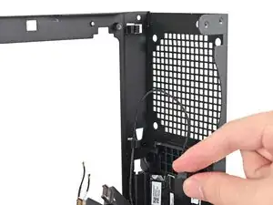
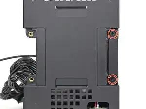
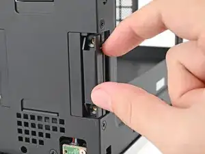
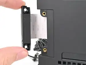
    • Use your Framework Desktop Screwdriver to remove the two 4.0 mm‑long Phillips screws securing the right antenna.

  39. tfae5caxwTOf4F4N
    tfae5caxwTOf4F4N
    IYywegXnonpvjJZq
    eH53SncFmgWlNM2C
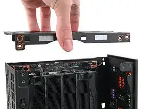
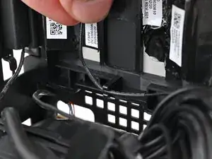
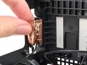
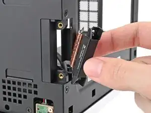
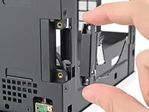
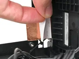
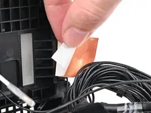
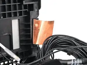
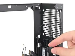
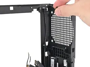
    • Lift the right antenna out of the chassis, making sure to thread the cable through the slot.

    • Remove the antenna.

  40. O46xDZ6XWnMOeZgT
    • Congratulations on completing disassembly! The remaining steps will show how to reassemble your Framework Desktop.

  41. UYxFUHe5udUTByi1
    UYxFUHe5udUTByi1
    uAFlQLtFOOZsjetn
    JDTUC51CVaDGjxWI
    • The replacement antennas look similar. The right antenna has a short, black antenna cable.

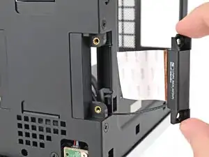
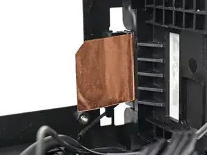
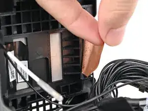
    • Place the replacement right antenna into its slot on the chassis, making sure to thread the cable through the slot.

  42. spMyWUiFdEDvCF2m
    spMyWUiFdEDvCF2m
    qPbYM5ttjKfawEpE
    • Use your Framework Desktop Screwdriver to install the two 4.0 mm‑long Phillips screws securing the right antenna.

  43. gvT1pSWRhKmEHb2F
    gvT1pSWRhKmEHb2F
    BPUMl1wlGYSkVaXL
    • Remove the liner from the back of your replacement right antenna.

  44. sZ3CeIAbCPx4QQdR
    sZ3CeIAbCPx4QQdR
    IMNsM3TBoEIleU6E
    GOZEkfTcAKVchHme
    • Press the right antenna's copper film onto the chassis and adhere it.

  45. ItD3sHUOGiouMqRr
    ItD3sHUOGiouMqRr
    WDfKsAWn2Rcyly1k
    • The left antenna has a long, black antenna cable with a white tip.

    • Place the replacement left antenna into its slot on the chassis.

  46. l33IEJVxUmn2upnF
    l33IEJVxUmn2upnF
    ACbyZlUV2NiXMmIF
    • Use your Framework Desktop Screwdriver to install the two 4.0 mm‑long Phillips screws securing the left antenna.

  47. wyiDR62U3Ke1mgRH
    wyiDR62U3Ke1mgRH
    kOHMnQowDODhhpeO
    • Remove the liner from the back of your replacement left antenna.

  48. SMnI2BocycNT6mc4
    SMnI2BocycNT6mc4
    4OeUYBA2FGX5TIWC
    jj2IDJJe5XqG6EAW
    • Press the left antenna's copper film onto the chassis and adhere it.

  49. rWYRE4QONFphfYZs
    rWYRE4QONFphfYZs
    15lD2AjjvDbHpQ3F
    • Press the black antenna cable into the plastic clip in the chassis.

  50. ZKRDACFyvQOXlnIY
    ZKRDACFyvQOXlnIY
    I5i5XeQLqIDeEjY6
    • Pull the antenna cables into their metal hook in the chassis.

  51. NS41oH14HK4LSOoX
    NS41oH14HK4LSOoX
    C13VUdoLooBrfxWI
    • Push the power button cable into its rubber clips on the chassis.

  52. 1pbDabnBlybxpxfR
    1pbDabnBlybxpxfR
    XGDnmYLkE611OU5f
    Ldf4MADkyZ4lYUWn
    • Grab the Mainboard by its heatsink and slide it into the chassis.

    • Align the rear ports with its cutout and the screw posts with the screw holes on the Mainboard.

    • You'll feel the Mainboard rest onto the screw posts when it's aligned properly.

    • Make sure no cables are trapped underneath the Mainboard before continuing.

  53. 6QT2ViU5b4DyOSPh
    6QT2ViU5b4DyOSPh
    GYESwKSXPtaUdCsk
    • Use your Framework Desktop Screwdriver to install the four 8.2 mm‑long Phillips screws securing the Mainboard.

  54. KKGSWfXbGxwis55s
    KKGSWfXbGxwis55s
    hh5DFeYu1pPbSNh2
    • Slide the power button cable over the nine-pronged connector on the Mainboard.

  55. ToRDBnSEvmKlRFQX
    ToRDBnSEvmKlRFQX
    Y6eeDNETENl5TvKI
    • Rotate the Desktop onto its left side so the underside of the Mainboard is facing upward.

  56. rBNQpOwhokKgiOnM
    rBNQpOwhokKgiOnM
    jpfXdqEyLRUxeVgW
    • Hold the Wi-Fi module by its edges. Don't touch the gold contacts with your fingers. If you do, wipe the contacts with a clean, lint-free cloth to remove any finger oils.

    • Align the Wi-Fi module's gold contacts and notch with the socket on the Mainboard.

    • Insert the Wi-Fi module into the socket at a shallow angle. The gold contacts should mostly be covered by the socket.

    • The Wi-Fi module fits into the socket in one orientation. If it doesn't fit, try flipping the module.

  57. ExRvaYJxwJXYdCHv
    ExRvaYJxwJXYdCHv
    WTBDIMuxbEDeIock
    nTPdXPoBKEOsdWTf
    • Hold the Wi-Fi module down with your fingers.

    • Position the black antenna cable connector over the left Wi-Fi module's coaxial socket.

    • Tweezers can help position the connector.

    • Use your finger to press the connector into place. You should feel a faint click, and the cable will stay attached to the socket by itself.

    • These connectors are very delicate! If the connector doesn't feel like it's clicking in place, reposition the connector and try again.

    • Repeat the procedure with the white antenna cable.

  58. GlIPQUIxutUhOnWU
    GlIPQUIxutUhOnWU
    IGUBlRNHSdUOhu1s
    Xmb5xxeeVaGML35q
    • Hook the Wi-Fi bracket over the corner of the Wi-Fi module opposite the antenna cables.

    • Rotate the bracket over the Wi-Fi module, making sure the screw hole isn't being obstructed by the antenna cables.

  59. dq5P24ICgQLROhlh
    dq5P24ICgQLROhlh
    sNjMCEjFw3MLQGZk
    • Use your Framework Desktop Screwdriver to install the 7.0 mm‑long Phillips screw securing the Wi-Fi module.

  60. HSTZqtf6lHnAUqCI
    HSTZqtf6lHnAUqCI
    iPQSPICPHP2RV2Xo
    • Rotate the Desktop so it sits upright on your work surface.

  61. RWGihWLmmycq33wQ
    RWGihWLmmycq33wQ
    jJ65ruZpe2BB1LD5
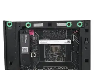
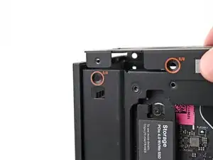
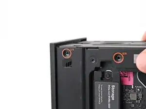
    • Place the top plate on top of the Desktop, making sure it slots into the chassis so the orange circles are visible.

  62. BBGrAcOycIPbPWpF
    BBGrAcOycIPbPWpF
    GIFOsosxKDJSSHQL
    • Make sure the matching screw hole on the top plate labeled "5/8" is slotted on the inside of the Chassis so that the orange circle is visible.

  63. MqBMBfqDDIa1SbgP
    MqBMBfqDDIa1SbgP
    TwAqhdodLT2mvRgu
    eP3AxDCYJItFGEDL
    • While holding the Desktop steady, use your Framework Desktop Screwdriver to install the eight 4.0 mm‑long Phillips screws securing the top plate.

  64. cekEOKTmLVTb3AXS
    cekEOKTmLVTb3AXS
    6OZTh1U1DaDZekaI
    5RSShLlsZbr3KyUD
    • Slide the Right Panel onto the right edge of the chassis, from top to bottom, and press it flat to ensure its clips are slotted into place.

    • There should be a small gap between the bottom of the Right Panel and the silver base.

    • Push the Right Panel towards the base of the computer to engage the clips.

  65. VYU3PPKs6NEt4Fxq
    VYU3PPKs6NEt4Fxq
    sIpKM3HNPARJLf4p
    • Lay the right side of the Desktop on your work surface so the Mainboard is facing upward.

  66. XWRyWAtrmTVrnPi1
    XWRyWAtrmTVrnPi1
    C4AbXmtMAJKCZKgZ
    • Slide the bottom Expansion Card cable into its socket on the Mainboard.

  67. RQgsNyGxwXdWeLQK
    RQgsNyGxwXdWeLQK
    qFGTO1HfoIhUI14t
    • Orient the CPU power supply cable so its clip is facing the heatsink.

    • Slide the cable into its socket on the Mainboard until you feel it click into place.

  68. ZDSImuhlL1stEJqN
    ZDSImuhlL1stEJqN
    g3QZgdngSLpUBXAO
    • Orient the main power supply cable so its clip is facing away from the heatsink.

    • Slide the cable into its socket on the Mainboard until you feel it click into place.

  69. ueOi4nSZINPOVDfL
    ueOi4nSZINPOVDfL
    LMgPWlDlpPUK2aX1
    • Slide the top Expansion Card cable into its socket on the Mainboard.

  70. 3pcZLc4uPnXnJOtM
    3pcZLc4uPnXnJOtM
    6XUIOKnsiynvQEke
    vw2BKQkZC6NK4blU
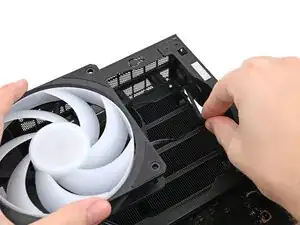
    • Orient the fan so its label is facing downward and the cable(s) is pointing towards the top of the computer.

    • If your fan has an arrow indicating airflow direction, make sure it's pointed towards the heatsink.

    • If you're using a different fan, orient it such that the fan is blowing towards the heatsink, not away.

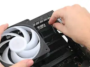
    • Lay the fan on top of the heatsink, making sure the cables are routed so they poke out of the hole on the top of the computer.

  71. hFPbMTrNTHeCxmPv
    hFPbMTrNTHeCxmPv
    vWExokOAUYshDsw5
    RdxvifGnFVTYZWJi
    • If the cables aren't routed properly, lift the fan up slightly and use your fingers to reposition the cables over the side of the heatsink.

    • If you're installing an RGB fan, make sure the "male" end of the RGB cable is covered and set aside in the corner of the chassis.

  72. erFIOJZXRZdkXA6u
    erFIOJZXRZdkXA6u
    qCPJhAm6rOxLw2yi
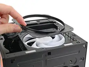
    • Lay the fan duct on top of the fan with the lip facing upward.

    • Align the screw holes on the fan duct with the ones on the fan.

  73. cJXFaJy5KgRfYfTS
    cJXFaJy5KgRfYfTS
    AqA3ZlysNECcaASm
    • Use your Framework Desktop Screwdriver to install the four 27.3 mm‑long screws securing the fan and fan duct.

  74. BL3ygwREO1Fw5aF1
    BL3ygwREO1Fw5aF1
    qsJCinJgtEvFxXwE
    • Orient the main fan cable so its two vertical lines are facing you.

    • Slide the main fan cable over the four-pronged connector labeled "APU Fan," making sure the orange label slots between the vertical lines.

  75. nFPEPcR1mudbNPCq
    nFPEPcR1mudbNPCq
    avKydg2UpSOudkfs
    yWpaheNAMq4suFkB
    • If you aren't using an RGB fan, then skip this step.

    • Orient the RGB cable so the arrow is on the right side of the connector.

    • Use your fingers to slide the RGB cable over the three pronged connector located to the right of the "APU Fan" connector.

  76. goRkkAxLhNUigiCU
    goRkkAxLhNUigiCU
    eA5rRNWKIMJseyOy
    ZvgNCU23cJQjlA6l
    • Slide the Left Panel onto the left edge of the chassis and press it flat to ensure its clips are slotted into place.

    • There should be a small gap between the bottom of the Left Panel and the silver base.

    • Push the Left Panel towards the base of the computer to close the gap and engage the clips.

  77. iIGHoTNwTjk6CsYT
    iIGHoTNwTjk6CsYT
    2bSMInO1IvGGlGdY
    V2XKH5ItaYfTBjxB
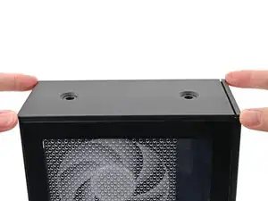
    • Orient the Top Panel so its arrow is pointing towards the rear of the computer.

    • While holding the Top Panel at a slight downward angle, slide it across the top of the chassis (from rear to front) until you feel its clips catch.

    • There should be a small gap between the Top Panel and the front of the Desktop.

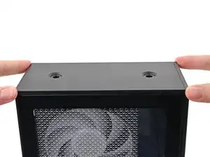
    • Lay the Top Panel flat on the chassis to align the remaining clips.

  78. 5jqYIJjCMYTIluBK
    5jqYIJjCMYTIluBK
    1HnNsOxjfWH3CW2A
    • While securing the computer with one hand, use the other hand to slide the Top Panel towards the front of the computer to close the gap and engage the clips.

  79. wMSbHEseVBHs4sQl
    wMSbHEseVBHs4sQl
    RUiXT1LIuwYW1mgA
    • If you're installing the Handle on your Desktop, follow this step. Otherwise, skip it.

    • Place the Handle over the Top Panel screw holes.

    • While holding the Handle in place, twist the screw threads on both sides clockwise until they're snug on the Top Panel.

  80. QvoH6OkAy6SluuRN
    QvoH6OkAy6SluuRN
    E5MbWITINqhggrhU
    sJHXRSaGVTAJTLGA
    • Insert the top panel screw into its hole and twist clockwise until it feels snug.

  81. omEEwgWEsLJVJGtZ
    omEEwgWEsLJVJGtZ
    yT2GekLdu6iCeSiv
    sehBCxDWubPcnoTn
    • Repeat the same procedure for the other top panel screw.

  82. 6dIq2aLI3wcuuFRc
    6dIq2aLI3wcuuFRc
    QFF5xZUlxcXQmRow
    svPrkAZgMdvGMFrS
    • Use your finger to close the two D-rings on the top panel screws.

Conclusão

You finished fixing your Framework Desktop!

Take your e-waste to an R2 or e-Stewards certified recycler.

If you need help, contact Framework support.

Alex Diaz-Kokaisl

Membro desde: 16/01/22

227430 Reputação

0 comentários