Introdução

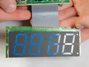
Use this guide to replace a faulty display or fix the wire connection between the circuit board and the display in an electrohome EAAC475 .

  1. XFDb1OVYqNGONIaF
    XFDb1OVYqNGONIaF
    3wDLevhIGvDI4xEM
    • Remove the 10 mm Phillips #1 screw from the battery cover.

    • Remove the battery cover.

  2. U6WpDqilOukLlxPF
    • Remove the flat lithium battery.

  3. 1XHnEkrF3vtQTDDP
    1XHnEkrF3vtQTDDP
    TWZMljLgpfWPkP61
    • Disconnect the radio from all power sources.

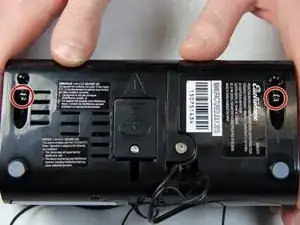
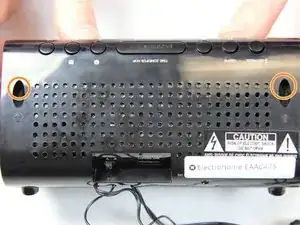
    • Remove the two 10 mm Phillips #1 screws from the bottom of the device.

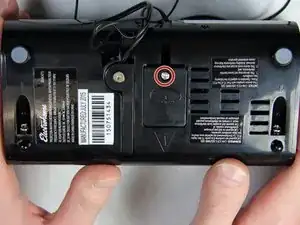
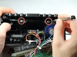
    • Remove two 10 mm Phillips #1 screws from the back side of the device.

  4. 212OTpjVqZw2HIex
    212OTpjVqZw2HIex
    Mw6XvMyAimAJ2nuL
    WQFtEHmkbcrcNjbB
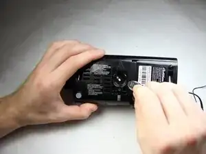
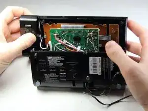
    • Carefully and slowly pull the lower case away from the rest of the device.

    • Do not completely separate the lower case. There are several wires connecting the two halves of the device.

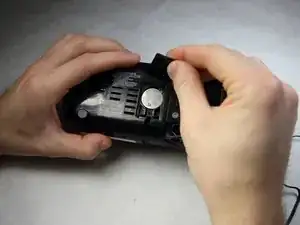
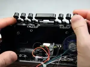
    • Flip the device over to access the button assembly.

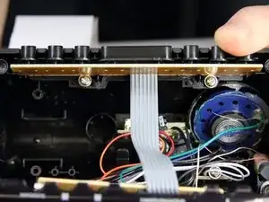
    • Slowly remove the button contact board from the assembly.

  5. hO4iDecJ5q3rQZEf
    hO4iDecJ5q3rQZEf
    iNmFr4kL1lmpwHO1
    • Remove the two 7 mm Phillips # 1 screws holding the buttons.

    • Remove the plastic buttons.

  6. 1POWdbuFmYStigXi
    1POWdbuFmYStigXi
    UyjhOQmmwROCOt5C
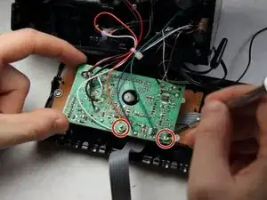
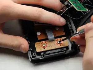
    • Remove the two 8 mm Phillips screws supporting the circuit board.

    • Pull off the circuit board to access the panels below.

  7. Wek3BeHTDLlIRU6H
    Wek3BeHTDLlIRU6H
    1sWBZHf5U6dZwTUI
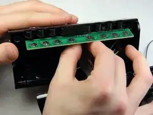
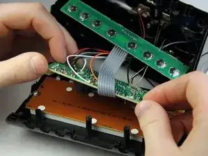
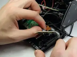
    • Remove the two 6 mm Phillips screws supporting the mini circuit board for the frontal buttons.

    • Remove the mini circuit board.

  8. LgLJYMpuSBLm24io
    LgLJYMpuSBLm24io
    MQQ6AyJ2Osr5XgQH
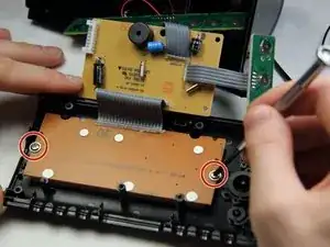
    • Move the now free circuit boards away from the display.

    • Remove the final two 7 mm Phillips screws securing the display.

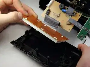
    • Pull the display screen away from the casing.

  9. vnGsqdOLNGdAPUyO
    • You have successfully accessed the display.

    • Replacing the display with a new one will be challenging as soldering and connecting micro wires are necessary.

    Hi, thanks for the tuto. You can also remove the white cover with blue digits to access individual leds on the PCB and only replace the faulty led (probably 0603 SMD white). Regards.

    Pierre Le Gargasson -

Conclusão

To reassemble your device, follow these instructions in reverse order.

Sohail Khatri

Membro desde: 16/02/16

201 Reputação

0 comentários