Introdução
-
-
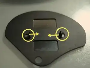
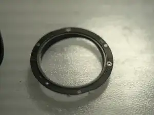
Push the pins inward, ONE side at a time, then lift the side from the bottom of the main body, to free it from socket. Then take care of the other side.
-
The pins
-
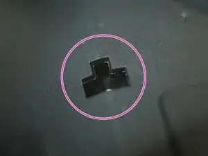
The socket
-
-
-
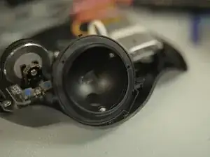
Remove the track ball (THE ball itself)
-
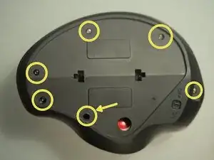
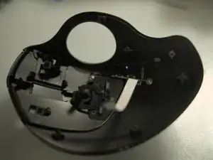
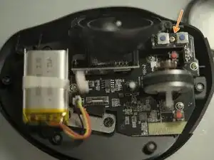
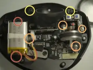
Remove 6 self-tap screws. The one pointed by an arrow needs a long thin philip head screw driver
-
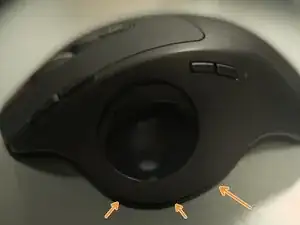
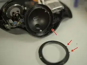
Apply a little bit prying force bear the ball socket, to open the bottom.
-
-
-
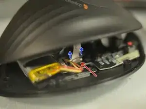
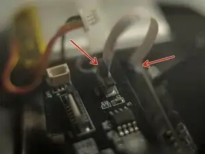
Unlatch the FPC connector by:
-
Push the black plastic latch up. Using tweezers.
-
Pull out the top cover FPC.
-
-
-
Same type FPC connector. Handle it as before. But, there's a drop of glue, removing it might damage the connector and/or the cable. Skip this if not intent to replace the tracking sensor.
-
-
-
To remove battery, remove 2 screws. (optional)
-
Remove 4 screws for the PCB
-
Remove 2 screws for the sensor
-
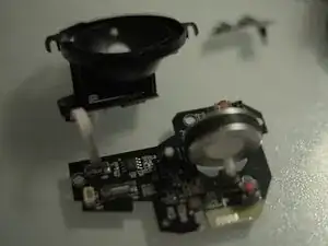
Lift main PCB and the sensor module (ball socket) off the bottom case.
-
-
-
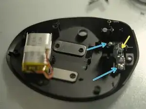
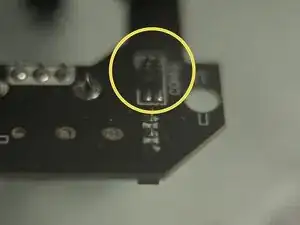
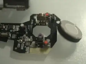
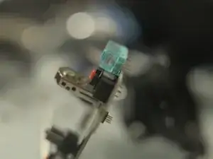
Noticed the 4-pin socket? There is a 4-pin pinheader under main PCB mating with it. should plug them back together while reassembling. Sorry for the shallow DOF, shot really close up and under poor lighting.
-
Remove 2 screws. Then remove the type-C module.
-
-
-
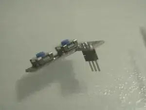
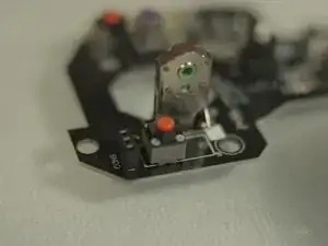
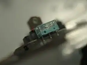
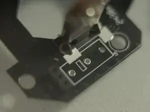
Original switch is silent 2-pin square type. It's totally interchangable with common 3-pin mouse switches (Omron D2F type).
-
To reassemble your device, follow these instructions in reverse order.