Introdução
Ferramentas
-
-
Unlatch battery compartment door.
-
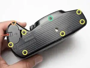
Remove one 1.7 x 4.0 mm screw.
-
Remove six 1.7 x 2.5 mm shoulder screws.
-
Remove one 1.7 x 2.5 mm long shoulder screw.
-
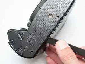
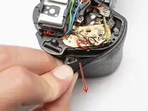
The bottom cover may be adhered with double sided tape in some locations. Use a spudger to gently work it loose.
-
-
-
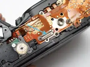
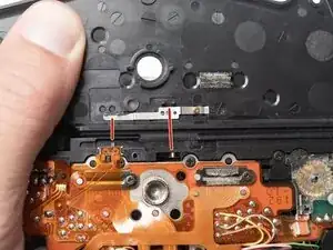
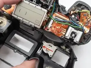
Check that the physical panorama switch on the bottom cover and the electrical switch mate properly.
-
-
-
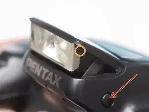
Push button to pop up the flash.
-
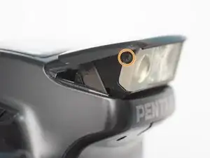
Remove two 1.7 x 2.5 mm screws.
-
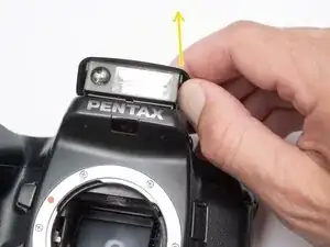
Detach snaps by lifting the side of the flash cover, bending it up and away from the housing.
-
Push flash back down to the stored position.
-
-
-
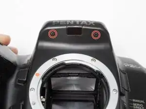
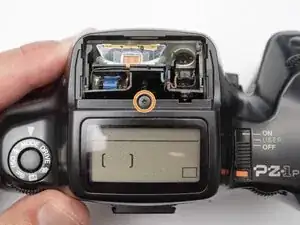
Remove two 1.7 x 2.5 mm screws underneath the pop-up flash.
-
Remove one 1.7 x 2.5 mm panhead screw above the pop-up flash.
-
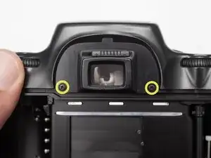
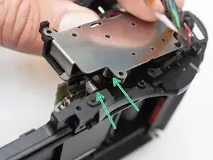
Remove two 1.7 x 2.5 mm shoulder screws near the eye piece.
-
-
-
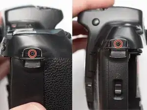
Remove two 1.7 x 2.5 mm shoulder screws by the strap lugs.
-
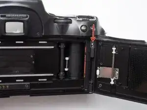
Remove one 1.7 x 6.0 mm screw inside the battery compartment.
-
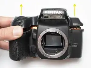
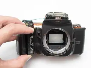
Lift off the top cover.
-
-
-
Check that the physical power switch and the electrical power switch are both in the same position before installation.
-
-
-
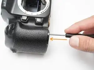
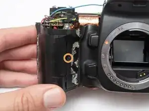
Peel off rubber covering from grip.
-
Remove one 1.7 x 5.0 mm screw.
-
Lift off the front body panel.
-
-
-
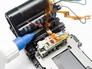
Connect a 10 kOhm high power resistor across the terminals of the flash capacitor for several seconds.
-
-
-
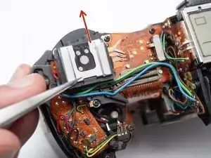
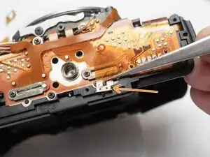
Remove the hot shoe spring. Lift the front of the spring and slide it towards the back of the camera.
-
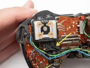
Remove four M1.7 x 6.5 mm screws from the hot shoe.
-
Remove black, brown, green, and blue wires from plastic guides.
-
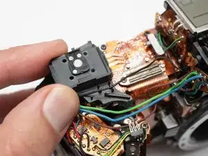
Lift off the hot show mount.
-
-
-
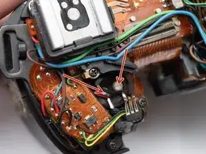
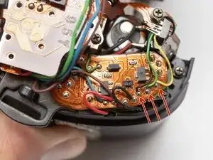
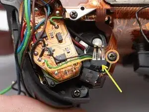
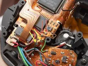
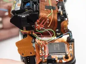
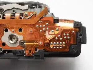
Unsolder the black, green and yellow wires for the command dial contacts.
-
Remove one 1.7 x 4.5 mm screw.
-
Lift off command dial contact.
-
-
-
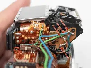
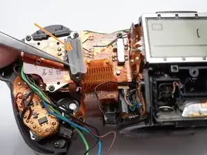
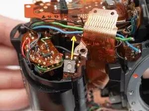
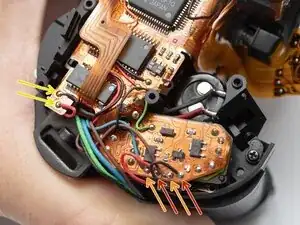
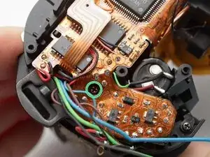
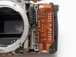
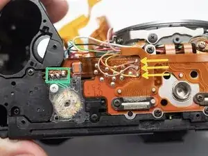
Unsolder the blue and green wires.
-
Unsolder the blue, green, brown and black wires from the flash relay PCB.
-
-
-
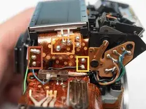
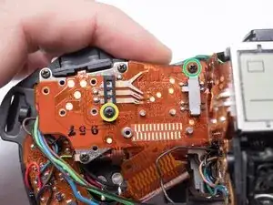
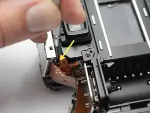
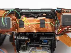
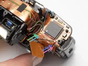
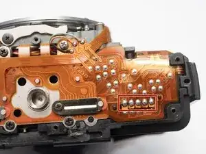
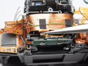
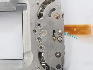
Unsolder three pads.
-
Unsolder three flex connections.
-
Unsolder two through-hole connections.
-
-
-
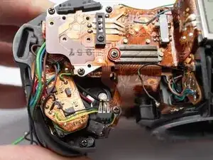
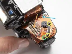
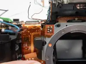
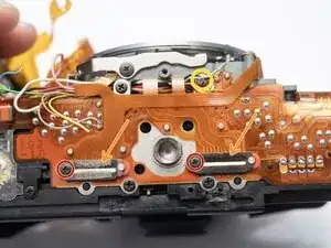
Remove one M1.7 x 2.5 mm screw.
-
Remove flex clamp and rubber pad.
-
Remove one M1.7 x 3.5 mm screw.
-
Remove one 1.7 x 3.5 mm screw.
-
-
-
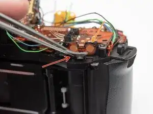
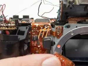
Remove one M1.7 x 2.5 mm screw.
-
Remove flex clamp and rubber pad.
-
Remove two M1.7 x 2.5 mm screws.
-
Remove one 1.7 x 2.5 mm screw.
-
Unsolder one blue wire.
-
-
-
Remove rubber dome pads for ME an IF buttons.
-
Detach button contacts from housing.
-
Push shutter release button up to free it from its retention post.
-
Detach snaps under the LCD frame.
-
Gently lift off LCD flex PCB.
-
-
-
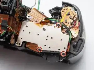
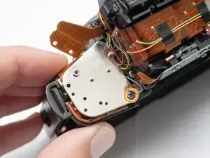
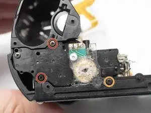
Remove three 1.7 x 3.5 mm screws.
-
Remove one 1.7 x 3.5 mm screw.
-
Remove both base plates.
-
Installation Notes: Make sure to attach the ground wire at this location when installing the plate.
-
-
-
Unsolder the red and black wires to the battery contacts.
-
Unsolder the blue and brown wires.
-
Unsolder the red and black wires to the charging motor.
-
-
-
Unsolder the red and black wires for the film advance motor.
-
Unsolder one green wire.
-
Unsolder two through-hole connections for the charge block contact.
-
Remove one 1.7 x 3.0 mm screw.
-
-
-
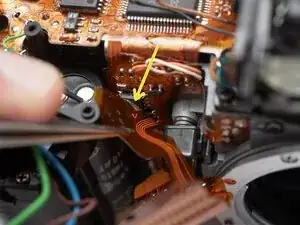
Unsolder one brown wire from the AF spot beam.
-
Unsolder two flex connections.
-
Unsolder the red and black wires for the buzzer.
-
-
-
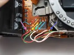
Unsolder the purple, green and brown wires for the aperture resistor.
-
Unsolder the red and yellow wires for the self-timer LED.
-
Unsolder the red and black wires for the TTL flash meter.
-
-
-
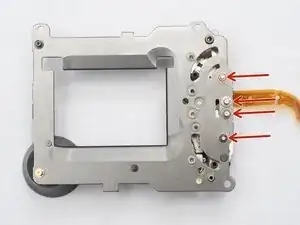
Unsolder five flex connections for the shutter unit flex cable.
-
Unsolder the white, black, and orange wires for aperture control unit.
-
Peal the shutter flex cable away from the main PCB. Apply isopropyl alcohol to loosen double-sided tape where necessary.
-
-
-
Unsolder the blue and brown wires to the aperture control solenoid.
-
Unsolder the red and black wires to the AF motor.
-
Unsolder the white, pink and green wires to the AF motor unit.
-
-
-
Unsolder five flex connections to the film door contacts.
-
Unsolder the black, orange, and gray wires for the AF motor unit.
-
Unsolder the orange, gray and yellow wires for the mirror release solenoid.
-
Unsolder three flex connections to the sprocket counter PCB.
-
-
-
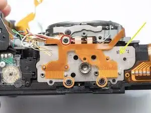
Remove two M1.7 x 2.5 mm screws.
-
Remove two flex cable clamps and rubber pads.
-
Remove one M2.0 x 4.0 mm screw.
-
-
-
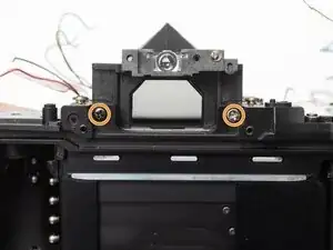
Remove one F1.7 x 3.0 mm screw.
-
Use tweezers to pull off one brass clip from the end of the adjustment post.
-
-
-
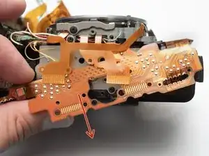
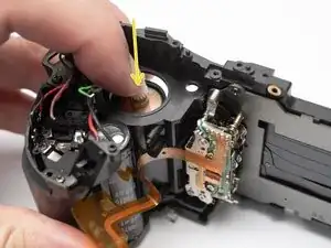
Begin by freeing the PCB from the bottom of the camera.
-
Work up and around the top.
-
Carefully work free the section between the grip and the lens mount.
-
Watch for areas where the flex may catch.
-
Slowly lift the entire PCB away from the camera looking for snags and wires that may still be connected.
-
-
-
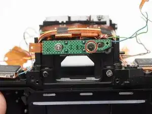
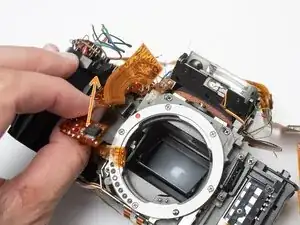
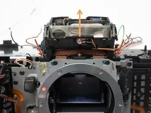
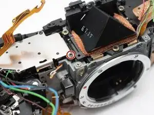
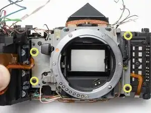
Gently pull the front housing block away from the main camera chassis.
-
Check for shim washers. Remove if loose and note their positions.
-
-
-
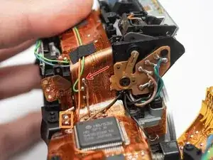
Charge the mirror box by pushing this lever forward until it catches. The mirror should be in the lower/viewing position.
-
Position the white aperture release lever to the right.
-
-
-
Push this lever to the right to release the mirror. It should flip up into the taking position.
-
Push this lever forward to charge the mirror and return it to the lower/viewing position.
-
-
-
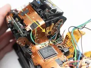
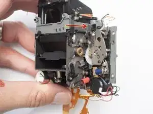
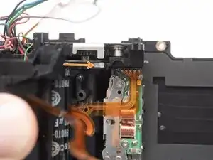
Turn the indicated gear to the right.
-
Keep turning until the mirror charge lever is up, or towards the rear of the camera.
-
The shutter charge lever should sit to the right as well.
-
Make sure that the shutter charge lever on the charge block is to the right of the lever on the shutter unit when installed.
-
-
-
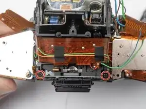
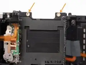
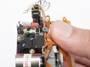
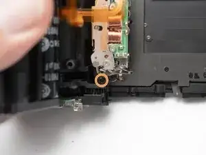
Remove two D1.7 x 7.5 mm screws.
-
Remove one D1.7 x 5.0 mm screw.
-
Push the charging motor down a few millimeters. This will allow access to one of the shutter unit screws while avoiding more significant disassembly.
-
-
-
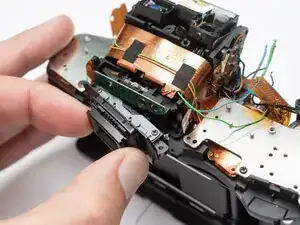
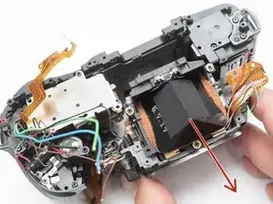
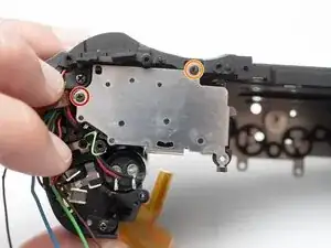
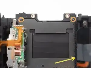
Detach the shutter flex cable from the camera chassis. Use isopropyl alcohol to loosen the adhesive if necessary.
-
Remove three D2.0 x 4.0 mm screws.
-
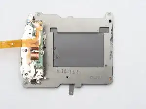
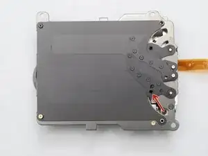
Remove the shutter unit.
-
Replace the foam light seal on the right hand side if necessary.
-
-
-
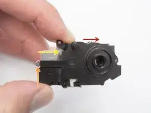
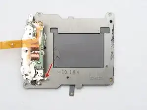
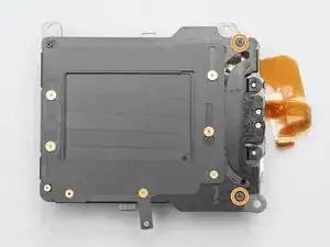
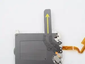
Discharge the shutter before beginning disassembly with the shutter release lever.
-
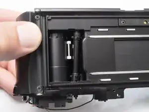
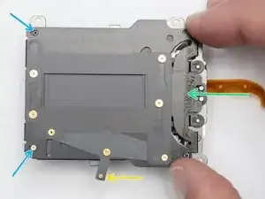
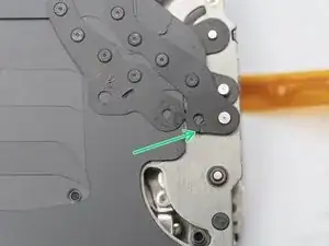
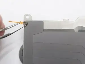
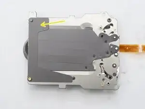
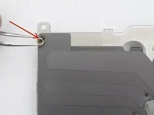
Remove two screws.
-
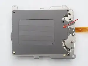
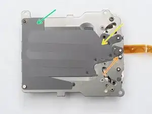
Move the panorama lever so the blinds are in the frame.
-
Push the back plate to the left...
-
Moving the two posts into the larger opening of the key holes.
-
Lift off the back plate.
-
-
-
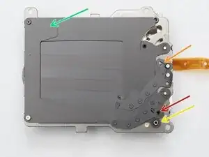
The opening curtain may come free from this post when removing the back plate. Remount it before proceeding.
-
Remove closing curtain helper spring.
-
Remove rubber damper.
-
Remove curtain guide.
-
Remove spacer bushing.
-
-
-
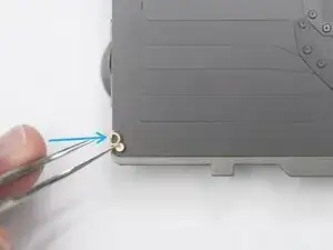
Unmount the opening curtain from the driving post. The curtain will want to move to the top of the frame.
-
Unmount the opening curtain from the pivot.
-
Continue rotating the curtain until the blades are collapsed and completely vertical.
-
Lift the opening curtain from the last post. Look for the helper spring underneath.
-
Installation Notes: Install the curtain in the same manner but reversed. Make sure the helper spring gets properly attached on the edge of the curtain arm as shown.
-
-
-
Remove spacer bushing.
-
Remove opening curtain helper spring.
-
Remove closing curtain.
-
Remove curtain guide.
-
Installation Notes: When installing the opening curtain helper spring, make sure the straight leg is underneath the flange on the post.
-
-
-
Clean curtain pivots with isopropyl alchohol.
-
Clean any residue from the shutter frame and back plate.
-
Clean the curtains where they interface with the pivots.
-

To reassemble your device, follow these instructions in reverse order.