
Introdução
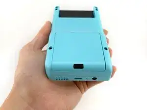
This step-by-step disassembly guide is intended for ModRetro Chromatic units sold on or after mid-2025. Please ensure you're using the correct guide for your device.
To verify: if the text beneath "Chromatic" says "1st Edition," this is the wrong guide. If it's blank, you're in the right place.
Use this guide when modifying or replacing components on the Chromatic.
Ferramentas
-
-
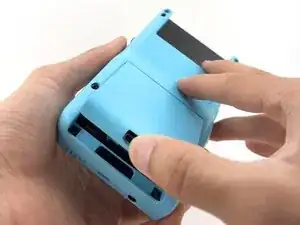
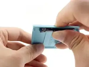
To remove the battery cover, push upward on the battery cover lock. The battery cover will pop open.
-
Lift the battery cover off and set aside.
-
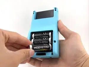
Remove the batteries.
-
-
-
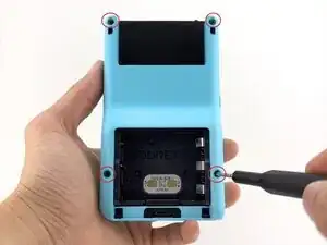
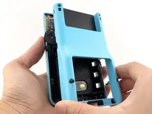
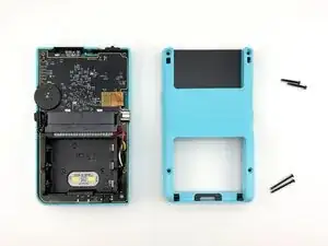
Remove the back shell screws (x4) using a Tri-wing Y1 Screwdriver.
-
Remove the back shell by lifting away from the device.
-
-
-
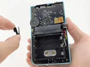
Remove the menu button by lifting it off the post. It will remove with little to no resistance.
-
-
-
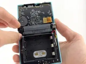
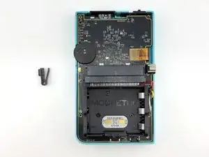
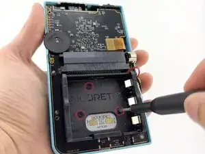
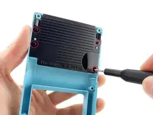
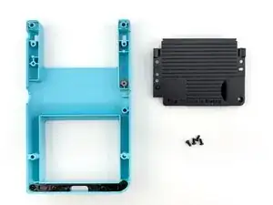
Remove the battery tray screws (x3) using a Tri-wing Y1 Screwdriver.
-
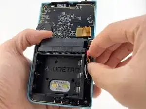
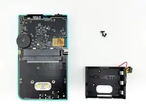
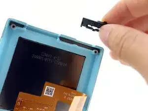
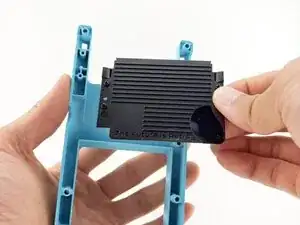
Remove the battery tray connector.
-
-
-
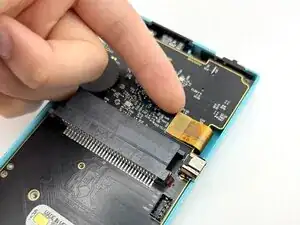
Carefully lift the LCD screen ribbon cable from the PCB.
-
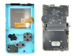
Carefully remove the PCB from the front shell.
-
-
-
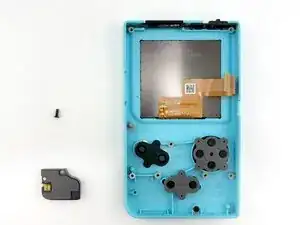
Remove the speaker module screw (x1) using a Tri-wing Y1 Screwdriver.
-
Carefully remove the speaker module from the front shell.
-
-
-
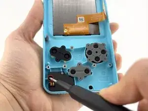
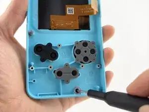
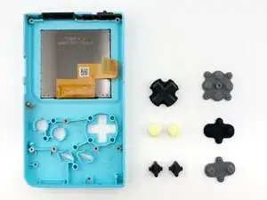
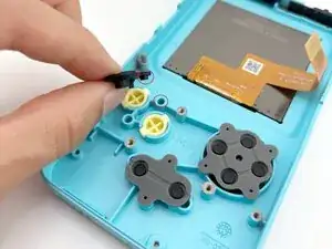
Remove the rubber button membranes (x3) from their pockets.
-
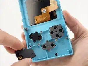
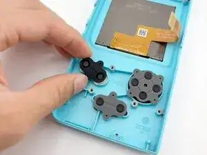
Remove the buttons and the D-pad from the shell with tweezers or by hand. If you flip the shell over, they will fall out freely.
-
-
-
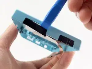
Carefully separate the IR window by gently wedging a plastic spudger between the IR window and the front shell.
-
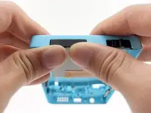
Note the side with the lip is inserted towards the front shell first.
-
Press in firmly until fully seated against the shell.
-
-
-
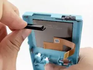
Remove the power switch by lifting away from the front shell. It will remove with little resistance.
-
-
-
Remove the latch catch screws (x4) using a Tri-wing Y1 Screwdriver.
-
Gently push the latch up from the back using your finger.
-
-
-
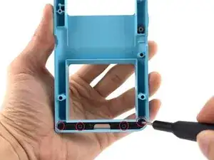
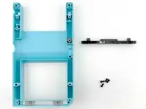
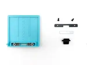
Remove the screws (x2) securing the latch cover using a Tri-wing Y1 Screwdriver.
-
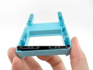
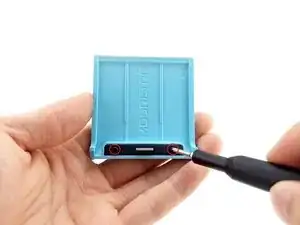
Remove the door plate spring by fully depressing the battery cover lock. The spring should pop out.
-
Once the spring is removed, the battery cover lock can be removed without resistance through the underside of the battery cover.
-

To reassemble your device, follow these instructions in reverse order.