Introdução
We'll be taking apart the entire controller to access all the internal components, allowing us to clean or replace components.
Ferramentas
-
-
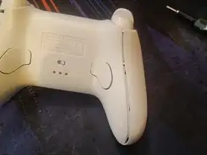
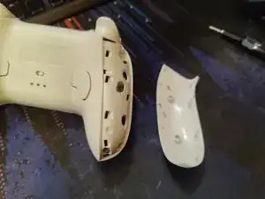
Pry open the panels on both sides of the controller.
-
Use a Torx 6 bit to unscrew the 6 screws, 3 on each side.
-
-
-
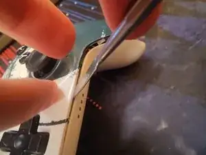
Pry off the front plate.
-
2 on the top on either side of the USB-C port
-
2 on the bottom on either side of the indicator lights
-
2 in the inner corner of the handles
-
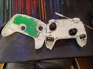
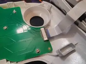
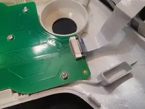
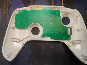
Carefully flip the front plate towards the left side as to not damage the ribbon cable.
-
-
-
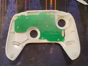
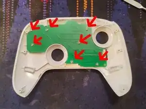
Unscrew the 7 short Phillips 0 screws from the circuitboard
-
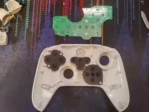
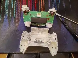
Lift the circuitboard up to access the buttons and conductive pads.
-
-
-
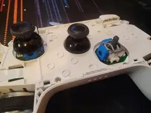
In order to gain further access, we should remove the stick covers, as they cannot pass through the holes of the structure plate.
-
They are friction fitted, and will come off by firmly pulling them upwards from the controller.
-
-
-
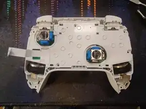
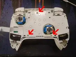
Unscrew the 3 Phillips 0 screws from the internal structure plate.
-
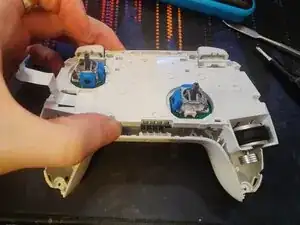
Lift up from the bottom of the controller
-
-
-
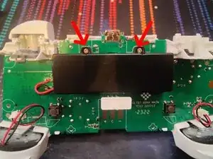
Unscrew the 2 Phillips 0 screws securing the battery casing.
-
Lift the casing downwards and out.
-
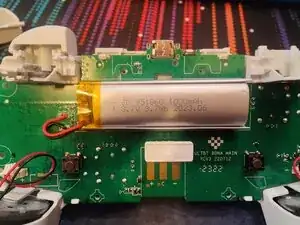
You now have access to the 1000mAh battery.
-
-
-
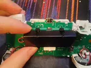
Pull the connector out, straight up from the board.
-
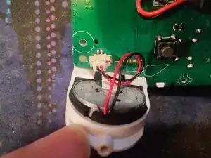
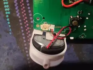
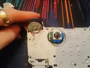
Flip the controller around and gently push the motors up from the socket. Careful so you do not snag and damage the cable when doing this.
-
-
-
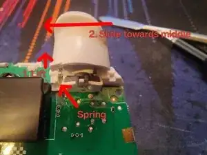
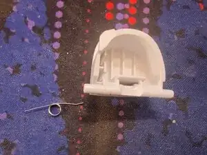
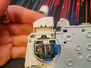
Take care not to lose the springs. There's one on both triggers, on the inner side.
-
Lift up the inner side of the trigger so it snaps out of the socket.
-
Remove the spring at this stage so you won't lose it. Using a tweezer may help if you have thicker fingers.
-
Slide the trigger inwards until it's out from the socket.
-
-
-
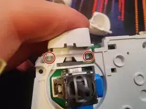
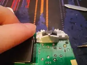
Disengage the clips on either side of the button by pushing them inwards to the middle.
-
Simply slide the button out.
-
-
-
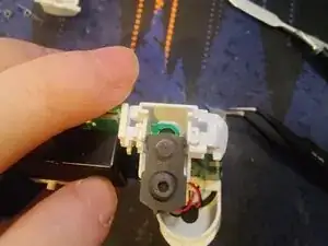
Unhook the gasket by gently lifting it over the pin.
-
Lift the gasket away from the plastic brace piece to dislodge the pin keeping it in place.
-
Once the gasket is unhooked, and the pin is dislodged, pull the gasket downwards to remove it.
-

To reassemble your device, follow these instructions in reverse order.
This guide can be followed to gain access to all internal parts of the controller for repair and cleaning.
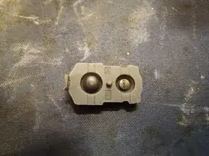
Common flaw due to a design flaw:
The rubber gaskets for the shoulder buttons and triggers is prone to failure after a year or two of use. This is due to a plastic piece in the triggers that push the conductive gasket into the sensors, but this plastic piece will over time start to cut into the rubber, leading to inconsistent and weaker output.
The best solution to fix this is to obtain a replacement part, but 8BitDo has discontinued this part due to their 2C lineup, which was made to avoid this specific issue entirely by introducing hall effect sensors for the triggers.
There are 3rd party parts available online, but they may have different properties than the originals, so keep this in mind.
My best suggestions is to obtain some good quality flexible silicone glue, and attempt to glue the broken part back together without affecting the qualities of the rubber piece in order to retain the original qualities and feel of the trigger.
Just keep in mind that the trigger itself needs manual modifications to permanently remedy this issue, which can be done by mounting some sort of bigger surface area to the trigger so it doesn't cut into the rubber.