Introdução
-
-
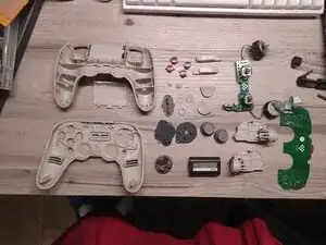
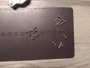
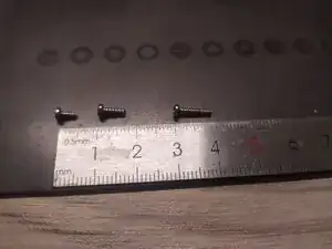
Screws List:
-
4 x "Torx 6" 7mm screws
-
6 x "Phillips 1" 10mm screws
-
10 x "Phillips 1" 5mm screws
-
-
-
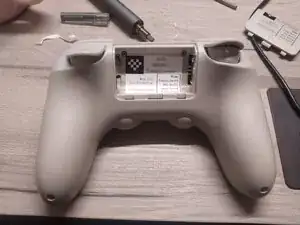
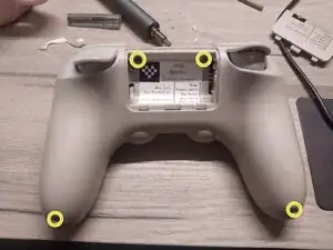
1. Open the back lid
-
2. Remove battery
-
Remove 4 screws:
-
2 screws in handles
-
2 screws under the label
-
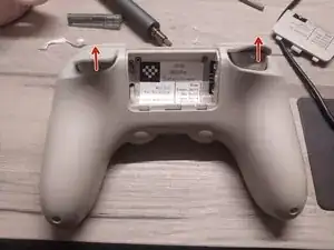
3. Unclip trigger's covers
-
JFYI: My label is not original
-
-
-
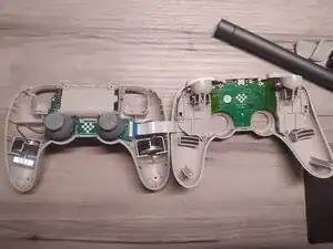
Using pry tool to split two parts. Start from handles.
-
Open to the right carefully - there is a ribbon cable
-
Slide ribbon cable lock to the right, then unplug ribbon cable
-
-
-
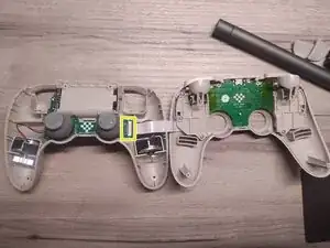
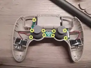
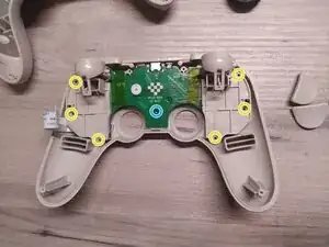
Remove 9 x "Phillips 1" 5mm screws
-
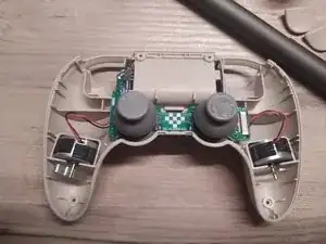
Remove stick caps
-
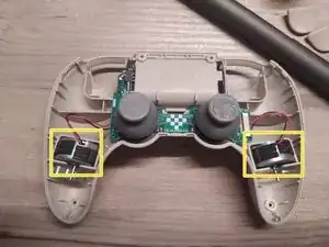
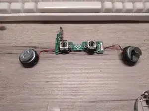
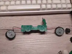
Eject vibration motors from slots in handles
-
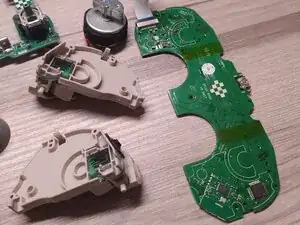
Eject circuit board
-
-
-
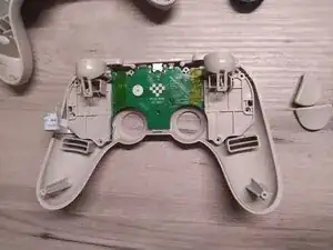
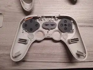
Remove 6 x "Torx 6" 10mm screws
-
Remove 1 x "Phillips 1" 5mm screw
-
Remove circuitboard with plastic attachments
-
-
-
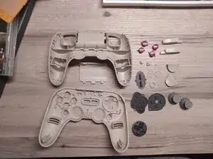
Deattach buttons, rubber pads and plastics aligners.
-
While assembling back, make sure, ABXY rubber pad cut angle is on top.
-
-
-
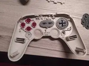
Unclip plasctic attachments with buttons and triggers. They are connected by pressure alone to the PCB
-
To reassemble your device, follow these instructions in reverse order.