Introdução

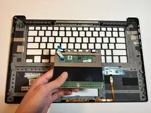
The touchpads of the Dell XPS 15 9550 line may undergo different types of failures throughout its lifespan, whether from liquid/debris damage or dead weighting. We introduce this replacement guide to help you in your journey in replacing these parts.

Part Tracking:

Because the trackpad is a part of the user’s frontal input interface, it is one of the most extensive parts to be disassembled within the device. We highly recommend keeping neat organization of the parts removed as each step goes by, especially the screws. Take note of their size, as one misplaced screw will throw off the whole reassembly.

Advisory Notes:

  • Power off and unplug your device before replacement/repair; Remove any external devices such as USBs, external SSDs, etc.
  • In addition to keeping track of your parts, you will be handling sensitive electronic parts, including exposed circuit boards and storage devices. Take precautions to avoid creating static such as grounding yourself regularly when interacting with these components. You can do so by touching solid, unpainted metal to release static charge from your hands. This will prevent damage and discourage dust from collecting in the workspace.
  • If you desire to clean these components, avoid using electronic vacuums and let cleaning solutions/solvents dry before reassembling.
  • To ensure the success of this replacement, please follow instructions of each step by going from top to bottom of the bullet-points.
  1. kSaWZZKecMVMWf5C
    kSaWZZKecMVMWf5C
    fHFTTAAQQ2ZtjLbO
    iSJxnZuJVF23sUra
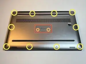
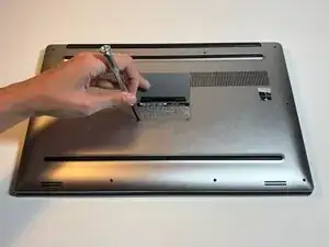
    • Lift up the system badge door.

    • Remove the two 8 mm screws using a Phillips #1 screwdriver.

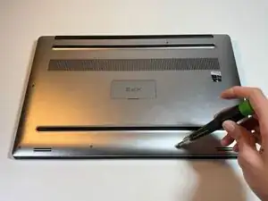
    • Remove the ten 3 mm screws around the edge of the back case using a T5 Torx screwdriver.

    • Remove the back cover.

  2. GPJHJ1bdvRuvOrCv
    GPJHJ1bdvRuvOrCv
    4w2mgOggQT25TQCQ
    uyLMLKXAEniH4ibx
    • Internal and sensitive components will now be exposed for the rest of this guide. Please exercise precautions, as provided by the introduction, including grounding yourself regularly.

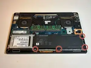
    • Remove the four 4 mm screws that hold down the battery using a Phillips #1 screwdriver.

    • On laptops with full length batteries, you may find 7 of these instead.

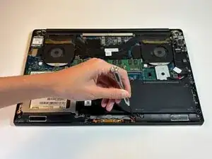
    • Unplug the cable connection between the system board and the battery, then remove the battery.

  3. TrRKleyxEiBLW2j3
    TrRKleyxEiBLW2j3
    4P46l4PoMCErRtst
    • Remove the hard drive bracket's four 4 mm screws using a Phillips #1 screwdriver.

  4. TWMGfDdpnbiVImEx
    TWMGfDdpnbiVImEx
    fNPvRuN3xw5ZPL1B
    5CWuJnld2jxFWbFt
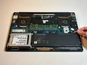
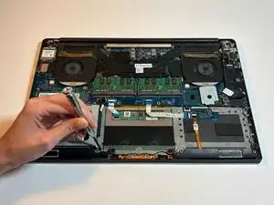
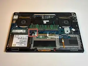
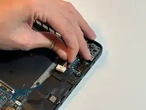
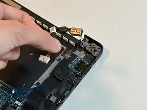
    • Unplug the cable in the upper-right corner of the hard drive connected to the system board.

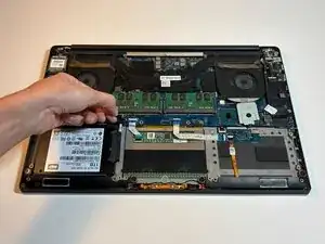
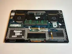
    • Remove the hard drive.

  5. MrpVOIQ6ylEILcfq
    MrpVOIQ6ylEILcfq
    VqAFUPcIq6YJsVqN
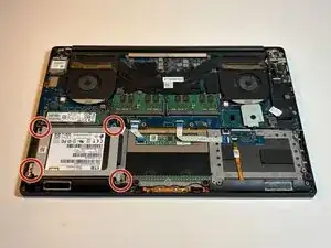
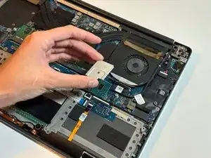
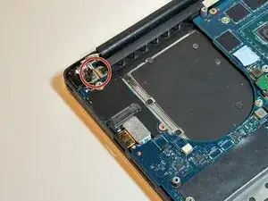
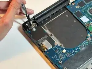
    • Remove the single 4 mm screw from the bracket in the upper left corner using a Phillips #1 screwdriver.

    • Remove the bracket.

  6. m63leFckVRJLcAlU
    m63leFckVRJLcAlU
    TRrHWs5T2E4TVeLi
    dZMpJN4gDMtjQFTg
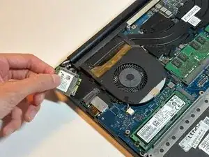
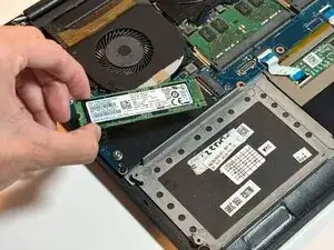
    • Unclip the antenna cables attached to the top of the wireless card.

    • Slide the wireless card out from its slot.

    • The antenna cable sockets are small and fragile; do not exert excessive force when pulling on the antenna cables. If you have difficulty disconnecting them, you may choose to use tweezers.

  7. 2AFfVuiJfWQkFMxN
    2AFfVuiJfWQkFMxN
    XM1odE6IdSNRCEGi
    JMDEatxBAO325FDZ
    • Solid-state Drive (SSD) cards usually have a bracket protecting them. For this step, you may simply unscrew the bracket and remove the card.

    • Remove the single 3 mm screw using a Phillips #1 screwdriver.

    • Remove the SSD card.

  8. ZruDihnn3IXtHqtR
    ZruDihnn3IXtHqtR
    JM6yNnEhbITDFkOf
    • Unplug the small white cable connection from the fan to the motherboard.

  9. I5Xo4hcOMEL3BYNR
    I5Xo4hcOMEL3BYNR
    NZGMrAXIPfIaRHQ2
    2UIcarP3Dq1yOHIo
    • Remove the two 4 mm screws from the fan using a Phillips #1 screwdriver.

    • Remove the fan.

  10. Y1rbvNpLZTWtEGnl
    Y1rbvNpLZTWtEGnl
    TGnvOOn6BmSSORSO
    5JJDCkeVC4xtmmN1
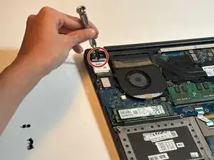
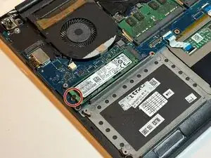
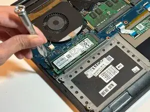
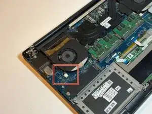
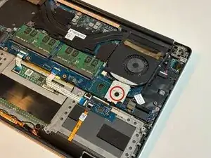
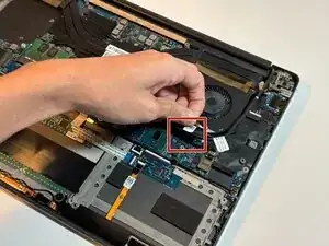
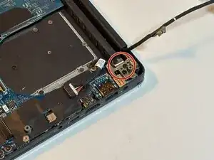
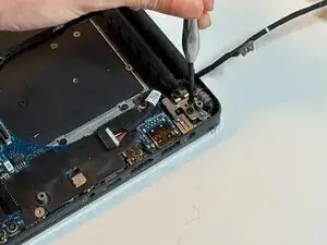
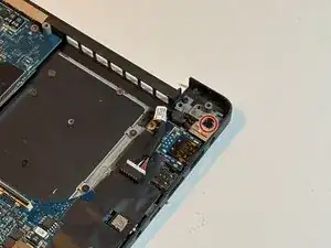
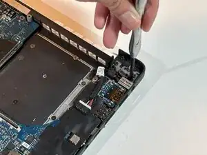
    • Remove the single 2 mm screw from the bracket below the fan on the right side using a Phillips #0 screwdriver.

    • Remove the bracket.

  11. RXVuLnDBeRukWtbc
    • Unplug the LCD cable connection.

  12. rgAOaaKLFDxRuePf
    rgAOaaKLFDxRuePf
    wCL6tA1agBaJFQAZ
    • Unplug the cable from the right-side fan that connects to the motherboard.

  13. oulR5LKYyekNmDy2
    oulR5LKYyekNmDy2
    op5PHc2PZvK4XPH5
    H5CYPP6J4CqRHRTB
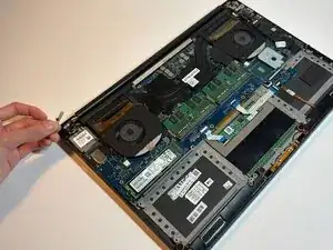
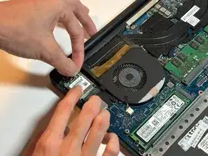
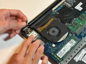
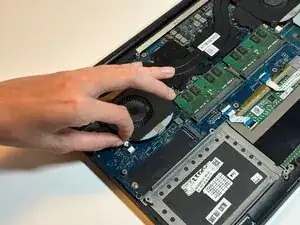
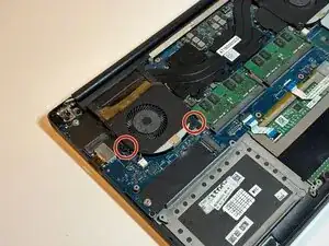
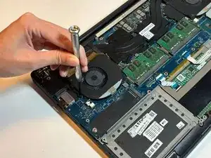
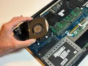
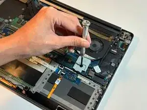
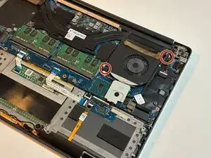
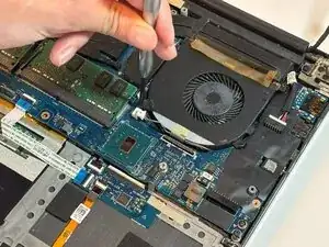
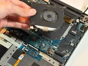
    • Remove the two 4 mm screws from the right-side fan using a Phillips #1 screwdriver.
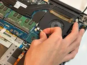
    • Remove the fan.

  14. YgvFnStyYBgZhPOW
    YgvFnStyYBgZhPOW
    Nn1FFFBEvGFoEwBt
    PYk2sH63ttvLktth
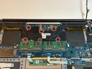
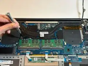
    • Remove the six 3 mm screws from the heat sink using a Phillips #1 screwdriver.

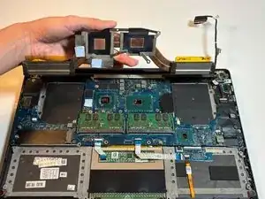
    • Remove the heat sink.

    • Your device's heat sink contact with the CPU should contain thermal paste during use; this ensures efficient heat exchange between your CPU and the heat sink during runtime. You can choose to clean away the thermal paste and replace it with a fresh application when you reassemble your device.

  15. oqA44DmDpmJDoPaC
    oqA44DmDpmJDoPaC
    svCsUqmtwMHHTyWD
    • Remove the three 5 mm screws from the left display hinge using a Phillips #1 screwdriver.

  16. VBFlFByb5GT3XphT
    VBFlFByb5GT3XphT
    wmdDXbmqRRieVfNT
    • Remove the three 5 mm screws from the right display hinge using a Phillips #1 screwdriver.

  17. 31a5dCZoTIOgKIqx
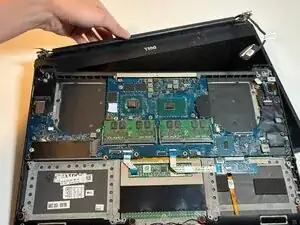
    • Remove the display from the palm-rest board. You may need to adjust and re-adjust the hinges in order to remove the display.

  18. LLKtmN3H2aFdIPXJ
    LLKtmN3H2aFdIPXJ
    nyKclSZwFQM5Ke1B
    • Remove the single 3 mm screw from the DC jack using a Phillips #1 screwdriver.

  19. WXIFApD3mOiXcgca
    WXIFApD3mOiXcgca
    MLn6bEL6LYmTrkdP
    • Unplug the white DC jack cable connection and remove the entire DC jack.

  20. 5dPqKJAEAWK2RKHK
    5dPqKJAEAWK2RKHK
    jf6tgx6ZPSgR43vx
    • Unplug the speaker cable connection.

    • This plug connection is small and difficult to pull off. Just like the wireless card antenna cables, you may choose to unplug this connection with other tools, such as tweezers.

  21. BWiNOHigYWMRL1sh
    BWiNOHigYWMRL1sh
    iT5lYvKpoweUAiru
    XRhb46hKbjWP5ep2
    • Remove the four 2 mm screws from the speakers using a Phillips #0 screwdriver.

    • Carefully unwind the speaker cables from the palm-rest board and remove the component.

  22. ydKmMGLaRldJp5Ks
    ydKmMGLaRldJp5Ks
    dIPQDbUoaaIduIRB
    JQZOLnvWOFddEVAY
    • Disconnect the two ribbon cables connecting the motherboard to the palm rest.

  23. Xe3GuOdLq3YnJZQ4
    Xe3GuOdLq3YnJZQ4
    23JnsEyPDTOFjaKd
    1iytpj3qWn2nCYSd
    • The system board is integral to your device's primary functions and can be easily damaged. Handle with extreme care and ensure you take pre-cautions such as grounding yourself prior to touching the component and storing the component in a clean environment.

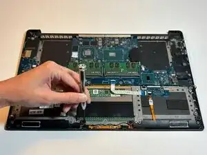
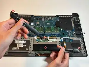
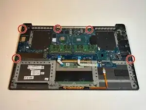
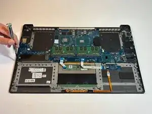
    • Remove the five 4 mm screws from the motherboard using a Phillips #1 screwdriver.

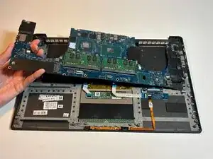
    • Remove the motherboard.

  24. rcHZZDmDlhuHjuUi
    rcHZZDmDlhuHjuUi
    KPnBPKPMFIvmUBJY
    VSEaAP5NRs1bHTUc
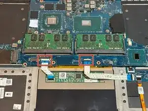
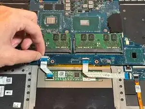
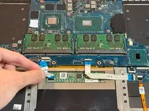
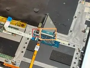
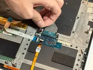
    • Lift up the black tab of the backlight connection and unplug the backlight cable.

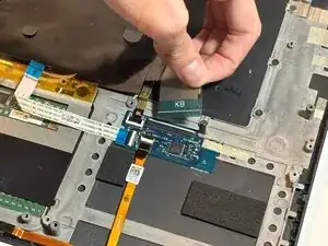
    • Lift up the white tab of the keyboard connection and unplug the keyboard cable.

  25. VIxtImc6sRPlyPe2
    VIxtImc6sRPlyPe2
    1VKEZJuSbvTakDCw
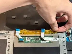
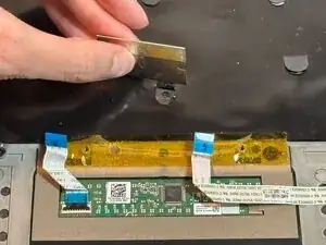
    • Lift away the yellow tape connecting the keyboard to the palm-rest board. It is not necessary to remove the yellow tape completely.

    • The Mylar covering the middle of the keyboard has stencil tabs; each stencil tab marks a screw under it. Lift up each stencil tab using a razor.

  26. IEblEb1qFAXsKneY
    IEblEb1qFAXsKneY
    g4LhHlLJqOhpXjP5
    RPymT4uQiIfSo6Wj
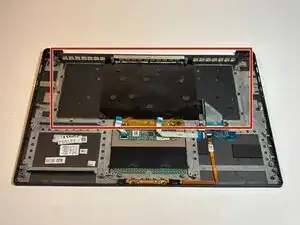
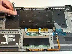
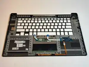
    • Remove the 31 1.5 mm screws from the keyboard, including the screws under the yellow tape and Mylar, using a Phillips #0 screwdriver.

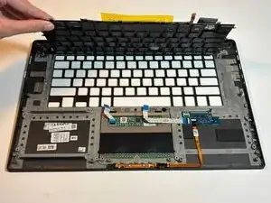
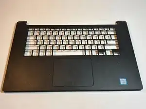
    • Remove the keyboard.

  27. xNfmwXVt5AVYYhmd
    xNfmwXVt5AVYYhmd
    WfE3vxQ21IWjBX2n
    • You are left with the entire palm-rest board component. At this stage, you may choose to replace your touchpad by replacing the entire palm-rest board. If you choose to replace only the touchpad itself, move to the last step.

  28. kUlXSt65TFWCruwr
    kUlXSt65TFWCruwr
    XfNyMvUGgHUYqGWL
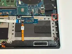
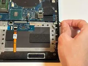
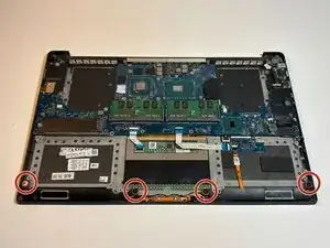
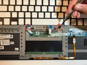
    • Remove the two screws above the touchpad using a Phillips #0 screwdriver.

    • Remove the touchpad.

Conclusão

To reassemble your device, follow these instructions in reverse order.

Felix M

Membro desde: 30/09/25

397 Reputação

0 comentários