Introdução
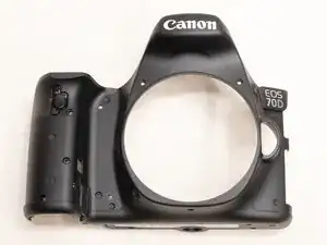
This guide will show you how to replace the front cover of the camera. This is useful both if you're replacing the front cover, or needing to gain access to other components in the camera such as the top cover.
Note that the Phillips #000 screwdriver is marked as an optional tool as you can always use the JIS #000 screwdriver in its place (JIS screwdrivers won't damage Phillips head screws).
-
-
Before beginning, remove the battery and SD card from the camera.
-
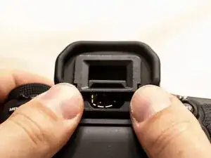
Using your thumbs, push up on the eyepiece to remove it.
-
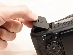
Remove the battery door.
-
Open the battery door to about a 35° angle.
-
Pull the battery door straight outwards.
-
-
-
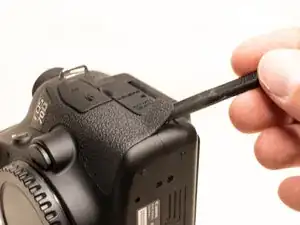
Using a plastic spudger tool, peel off the rubber grip on the left side of the camera.
-
Underneath where the rubber grip was, remove the following screws:
-
Three M1.7x5.5mm Phillips #000 screws
-
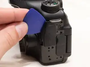
Pry off the plastic interface cover.
-
-
-
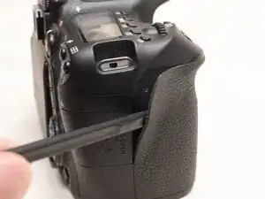
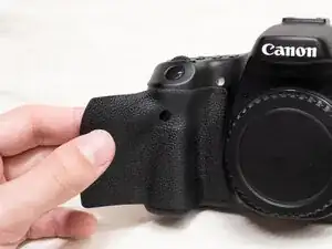
Using the plastic spudger tool, peel back the rubber grip on the right side of the camera to expose the screws.
-
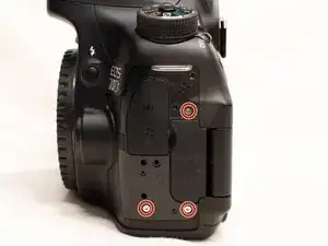
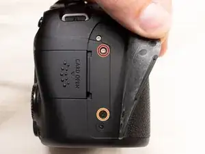
Remove the following screws underneath the right rubber grip:
-
One M1.7x3.0mm JIS #000 screw
-
One M1.7x3.5mm JIS #000 screw
-
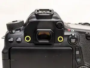
On the back of the camera, remove the following screws:
-
Two M1.7x5.5mm JIS #000 screws
-
-
-
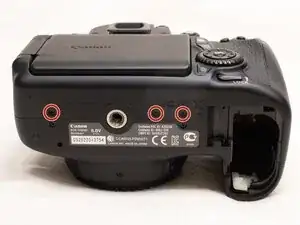
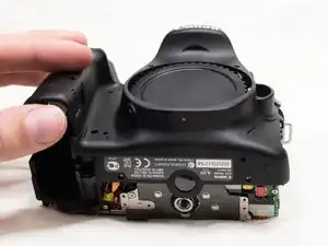
On the bottom of the camera, remove the following screws:
-
Three M1.7x3.0mm JIS #000 screws
-
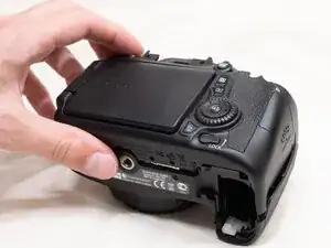
Slightly lift up the back cover from the camera, using a plastic spudger or opening tool as needed.
-
You can lift the back cover towards the bottom of the camera to get better access to remove the cables.
-
-
-
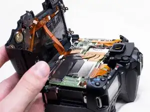
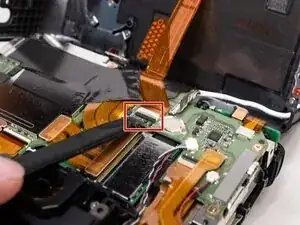
With a plastic spudger tool, gently lift up on the black locking tab on the ribbon cable connector.
-
Once the locking tab is lifted up, you can carefully pull out the ribbon cable.
-
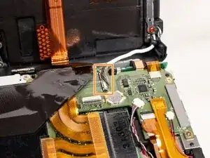
Use the plastic spudger to gently pry off the other cable connecting the back cover to the camera.
-
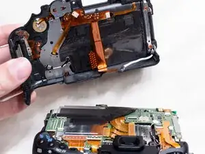
With both of the cables disconnected, you can finish lifting off the back cover from the camera.
-
-
-
Peel the right rubber grip off the rest of the way.
-
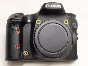
On the front of the camera, remove the following screws:
-
Two M1.7x5.0mm Phillips #000 screws
-
One M1.7x4.5mm Phillips #000 screw
-
Two M1.7x6.0mm JIS #000 screws
-
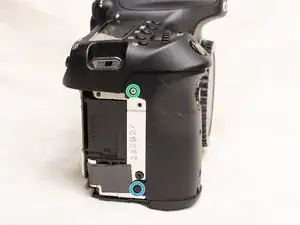
On the right side of the camera, remove the following screws:
-
One M1.7x3.0mm JIS #000 screw
-
One M1.7x3.5mm JIS #000 screw
-
-
-
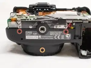
On the bottom of the camera, remove the following screws:
-
Two M1.7x3.0 JIS #000 screws
-
One M1.7x4.5mm JIS #000 screw
-
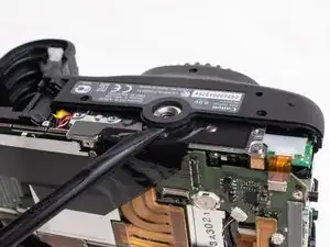
Use a plastic spudger to pry up on the bottom of the front cover and lift it over the tripod socket.
-
Pull the front cover off the camera body.
-
To reassemble your device, follow these instructions in reverse order.