Introdução
Firstly, if you haven't, DO NOT firmware update a working Meiki Lens as the firmware magic string seems generic and it can flash the wrong firmware and brick your lens permanently.
What should have been a repair tutorial turned into a cautionary tale...
In a moment of careless idiocy, I dropped the wrong firmware file into the folder the lens created as a USB mass storage device. The lens was updated and became non-functional, and no longer appeared as a USB device. There is no way back! I'll leave this guide so that no one else has to redo the work, only to hit a brick wall with the encrypted firmware and no parts from Meiki.
The correct Firmware site is here: https://meikeglobal.com/pages/firmware-u...
''I had gone to the wrong, old?? Chinese firmware site! http://www.mkgrip.com/down.html''
The above site has since been taken down!
I attempted using limited resources, datasheets and some questions to ChatGPT to put the tiny onboard STM32 ARM processor into DFU Mode where it will enumerate under USB, and can be programmed/re-flashed with the STM32CubeProgrammer.
I managed this! The pitch of the MCU pins made metering out individual pins very difficult, and soldering even a strand of copper wire to the pins nearly impossible, especially when I was using a metal magnetic cereal clip as a PCB holder, and working on top of a mini fridge with an iron more suited to through-hole!
I managed by some miracle and new equipment to replace the MCU and programmed it. I reassembled the lens, but it did not work and does not enumerate under USB! This is the same behaviour as the original MCU with its BOOT0 pin disconnected (which I blamed for the behaviour!). I now firmly believe the firmware is strongly encrypted, STM32 MCUs include AES encryption of IP protection (it has an entropy value of 7.9487), and it makes sense that the MCU will be set to deny read, so there is no way to obtain an unencrypted version of the firmware to load via DFU mode.
I reached out to Mieki to see if I could purchase a replacement PCB:
"Sorry, we do not sell this component."
If you brick your lens, you cannot recover it unless you can get a good PCB from a broken lens of the same type!
-
-
This is the easy part! Use a screwdriver,(PH000) to remove the two screws indicated in photo one.
-
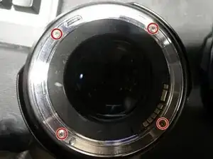
Use a screwdriver,(PH00) to remove the four screws indicated in photo two.
-
The plastic moulding is held in place by the four indicated clips, but it can just be pushed out from the inside
-
-
-
First carefully remove the flat ribbon cable indicated by the arrow. I used a small pair of smooth-jawed snipe nose pliers. You can also use your fingernails if they are long enough.
-
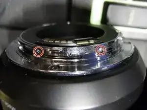
Once you have taken off the rear cover with the AF/MF switch. You should carefully remove the remaining flat ribbon cables. Then remove the two PCB retaining screws circled using
-
-
-
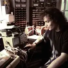
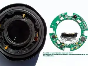
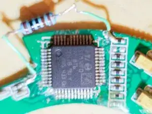
The logic board of the Meiki 85mm f/1.8 with the micro-USB I/O port. Is shown in the first picture alongside the Lens. It is basically an STM32 MCU with two motor drivers.
-
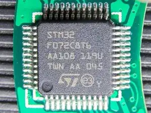
The second picture shows a macro shot of the STMF072C8T6 Microcontroller.
-
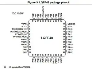
The Third picture is from the ST Data Sheet and shows the LQFP48 pin assignment.
-
-
-
When booting from the factory firmware, Pin 44 BOOT0 is held Low, 0V via a 10kΩ pulldown resistor. Pin 7 the NRST pin is held High at 3.3V via a 10kΩ pullup resistor which has a decoupling capacitor to 0v.
-
To boot in DFU mode, Pin 44 BOOT0 needs to be held high. At or close to 3.3v. Then Pin 7, NRST pin is momentarily pulled low to reset the MCU!
-
I did not know where BOOT0 was held down. So I unsoldered and bent up pin 44 and pulled it high via a 10kΩ through-hole pullup resistor! It worked, but pin 44 broke off when I tried to revert it, effectively destroying the MCU!
-
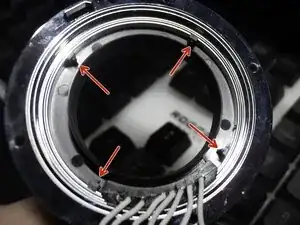
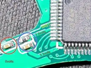
NRST : In 'picture 1, you can see the decoupling capacitor that you need to short momentarily, circled in red. For 3.3-volts for BOOT0 you can tack your pull-up resistor to the top of the 10kΩ NRST pull-up resistor or the adjacent decoupling capacitor, both circled in blue. You could scratch to the copper on the lower trace and tin it.
-
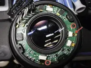
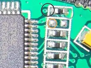
BOOT0 : In picture 2, you can see where BOOT0 pin 44's trace emerges from the back of the board connecting to a 10kΩ pulldown resistor! Black () Pin 36 under it is VDDIO2 and is at 3.3 volts! Orange (). Connecting a 1kΩ pull-up resistor here and to your mouse convenient 3.3 volts rail sets up the MCU for DFU mode!!!
-
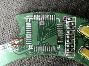
Butchered! : Picture 3 is the PCB minus the MCU (looking well butchered and worse for wear!). The Red square is where I took my 3.3-volts and the pink circles show where BOOT0 trace disappears under the MCU and where it emerges. [See Rework page]
-
-
-
As in Picture 1, shows a 6-band 1KΩ resistor is connected to 32swg wire, which in turn is soldered to the 3.3v trace at one end and the top of the 10KΩ BOOT0 Pulldown resistor at the other.
-
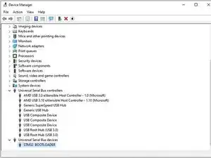
once your board is configured for DFU mode, connect it to the system you have installed the STM32CubeProgrammer software on and launch it. The board should have already enumerated under USB and the programmer will connect to it! Picture 2, Shows DFU's Bootload in device manager under Windows 10. Named as STM BOOTLOADER
-
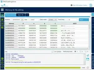
Picture 3, shows a screenshot after reprogramming. In the next pages, I will go through the programming steps.
-
-
-
Firstly, get the correct firmware from the Meiki site. You will have to extract the firmware .SKY file and rename the firmware to .BIN if it is not already named that.
-
With the PCB on a non-conductive surface, plug your USB in. Open the STM32CubeProgrammer and click the "Blue button" next to the "Green Connect button" and select USB! Now click Connect. The programmer should connect to your board and display info.
-
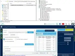
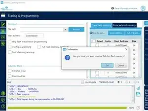
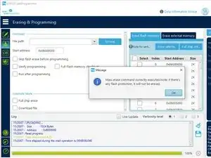
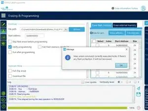
Now, click the second from the top green button on the left, selecting "Erasing and Programming". Centre right on the "Erase Flash Memory" Tab, click Full Erase. (Picture 1) Click OK to Erase. A message will display when the operation is complete (Picture 2)
-
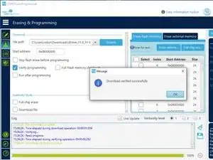
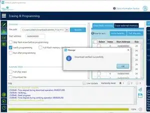
In the Download section, use Browse to select your firmware .Bin file. Click the "Verify Programming" checkbox, then click the "Start Programming" button. After the Programming and Verification completes you should see a confirmation dialog (Picture 3)
-
After this point I broke pin 44 off!! You, however, should unplug your board, carefully remove your 1KΩ BOOT0 pull-up resistor. Then Plug your board back into USB and see if a folder shows up as it did when the lens had the correct firmware. If it does reassemble your lens and test.
-
If it doesn't show up, you can test the board in the lens or go straight to putting the 1KΩ resistor back and repeating with another firmware image.
-
-
-
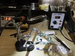
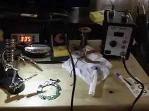
I purchased a very cheap Hot Air rework station $35 and I will be getting a new MCU!!
-
Working on mapping the I/Os a little
-
I reworked the PCB. Helping hands, solder paste and a flux pen were a must-have! I ran the 858D at around 333°C & air 4¾, I had the Iron at 312°C. I cleaned the pads, put solder paste, positioned the MCU and used the largest of the 3 nozzles to solder it. I had to rework with flux paste, Iron & braid, reheat flux and smallest nozzle. Hours of work.
-
Tonight, after two "USB Device not recognised" attempts and rework, the board enumerated, and I was able to erase, program and verify the firmware.
-
-
-
I reprogrammed the new MCU with the renamed .sky firmware image. As shown in these three images.
-
I removed the pull-up resistor, knowing from the voltage drop across it that the pull-down resistor was in circuit.
-
I re-assembled the lens, but it neither worked or enumerated. Whilst my replacement of the MCU may have stopped it from working. As we know, USB communications worked and the MCU ran, so it should of enumerated had the firmware run! Also, this is the same as how the original MCU behaved.
-
I need a clean DFU mode uncompressed/encrypted firmware image.
-
-
-
As an old tech from the eighties, maybe the one thing I didn't allow for was the modern obsession with "Intellectual Property". I thought the firmware may have been compressed, or even obfuscated. But I failed to realise that this protection was provided by ST and implemented in software and hardware.
-
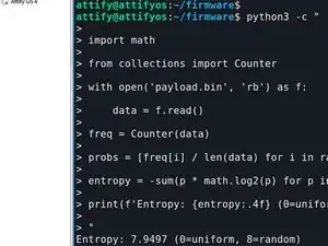
I worked on the firmware in a Linux VM but when I couldn't go any further, I asked an AI, it suggested I get the Entropy value from binwalker. It just returned me to a shell prompt after it helped me analyse the file it gave me a Python script to calculate entropy at 7.9497.
-
The encryption is almost certainly symmetric key encryption. Worse is that the hardware implements "No Read" which, if Meike had the foresight to use the strong enrytion ST provide in their development tools..
-
Then they would almost certainly employ no read to protect the unencrypted firmware being pulled out of the Microcontroller.
-
If you brick one of these lenses, the only way to possibly restore your lens to a functioning state is to get a good PCB from a physically broken lens of the same type. I asked Meiki do not sell replacement PCBs even though it is their Intellectual Property protections which prevent you from recovering the lens firmware...
-
From ST regarding IP protection: https://www.st.com/content/st_com/en/eco...
-
Do not update the firmware on a working Meiki Lens!