
Introdução
This guide helps you fix a Beoplay V1 TV which won't turn on. The reason is likely a dead super capacitor, a part which can be replaced for a few bucks. I was pointed to the solution by a thread in Beoworld forum and wrote this guide, hoping it will be easier for people to find and follow so they can fix their devices.
Note: While this repair isn't very complicated, it's quite demanding as the capacitor's negative terminal is connected to a massive ground plane. You need a heat gun or similar device to at least preheat the area - most soldering irons won't be able to apply sufficient power.
Ferramentas
Peças
-
-
Unplug the device from power and remove all other cables.
-
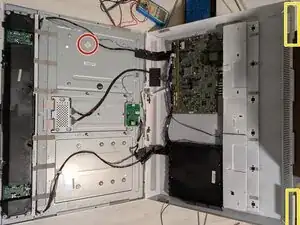
Lay the TV onto the ground, screen down. You need a working area of at least two times the TV's height. Make sure there are no small objects in your working area which could damage the panel!
-
-
-
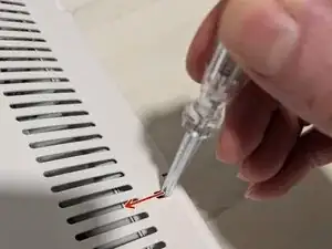
Using a screwdriver, press the lever holding each end of the stand away from the corner. Slightly pull out the stand.
-
Pull out the stand completely, alternately moving each end a little so you don't apply too much strain.
-
-
-
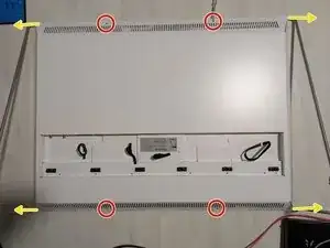
The case is held together by bolts on the TV's upper end.
-
Grab the back side of the case at the lower end and lift it slowly. The case will flip open.
-
Remove the cables going to the left speaker amplifier from the plastic clip holding them in order to avoid strain.
-
Open the case to about 120° and lean the back side to a wall or some other object. Make sure the object will stay in place!
-
-
-
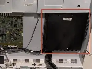
On the right side of the case, under the black plastic cover, you will find the power supply. You might want to check it to make sure it's okay.
-
-
-
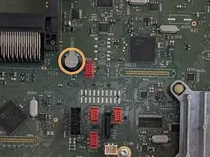
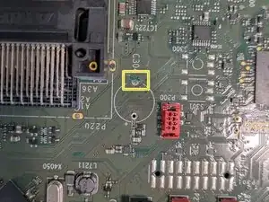
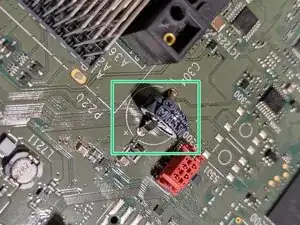
Take a close look at capacitor C304, right next to the black CI slot. This capacitor seems to be leaking its electrolyte quite frequently, the TV won't turn on when it's dead.
-
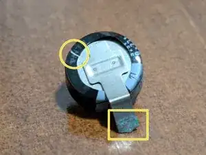
Check if you can see corrosion (discolouring) on the capacitor's pins or nearby components. The plastic sleeve is likely torn if electrolyte has leaked. If you observe any of the two, the capacitor is definitely dead.
-
If unsure, connect the TV to power, then disconnect again after a few seconds. Wait a minute or so and then use a multimeter to measure the voltage across C304 (between its positive top and ground). It should be about 1.9 V and be stable for quite some time. If you read a lower voltage, or it drops rapidly, the capacitor is faulty.
-
-
-
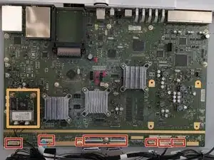
Disconnect all cables from the mainboard.
-
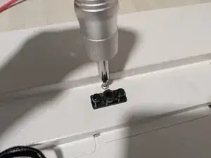
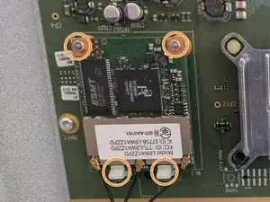
Remove the WiFi card and its screwed brass standoffs. The two plastic clips are bent back slightly so you can pull the card out. When reassembling, insert it into the clips first before pushing in the connector.
-
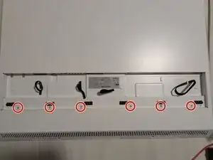
Remove the three Torx T10 screws with the black cable holders.
-
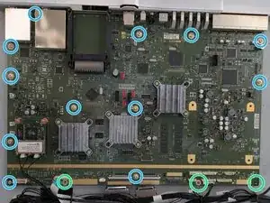
Remove the twelve Torx T10 screws holding the mainboard. It is secured by a pin, so it won't fall down.
-
Carefully pull out the mainboard. There's a large heat spreader in the back which may fall off. Reseat it in that case.
-
-
-
Use a soldering iron to unsolder C304's + pin. All soldering is done at the back side of the mainboard! Pictures show the front side.
-
Remove the capacitor by bending the - pin back and forth until it breaks. Be careful not to damage any of the traces underneath and in the vicinity! Clean the + pin's through hole from solder using a desolder pump.
-
Clean the area surrounding the capacitor with isopropanol and try to gently remove leaked electrolyte and corrosion.
-
Carefully heat the - pin's through hole with a hot air gun until the solder melts so you can pull out the pin's remains and remove the solder with your solder pump. This needs an excessive amount of heat, start with low temperature and raise it slowly (I ended up at 470° C). Don't start with too high temperatures to avoid damaging the PCB!
-
Insert the new capacitor; it doesn't have to have the same footprint, you may be able to bend the new capacitor's pins to fit the holes.
-
Solder the + pin with the soldering iron. On axial devices, the - pin is often marked (with -), and typically arrows are printed on the sleeve indicating the technical direction of current (+ to -), i.e., their tips point towards the - pin as seen in the second picture.
-
Use the heat gun to preheat the - pin (ideally, you have someone to assist you here). Apply solder, use your soldering iron to apply additional heat and make sure the solder connects to both the capacitor pin and the PCB's copper pad.
-
Alternative: If you can't heat the - pin's through hole sufficiently, you might look for another ground connection in the vicinity and try to connect the capacitor's - pin there. However, make sure not to short anything when running a wire across the PCB!
-
To reassemble your device, follow these instructions in reverse order.