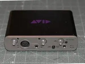
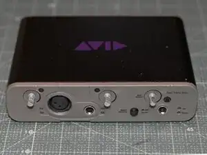
Introdução
Full disassembly and teardown of the Avid Fast Track Solo audio interface.
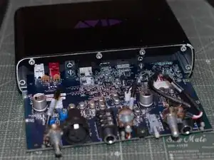
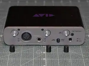
Follow this teardown to take off the chassis and access the internals of the Avid Fast Track Solo. This teardown can also be used in order to access, clean, or replace potentiometers or other components.
Before you begin, completely unplug all cables from this unit.
Ferramentas
-
-
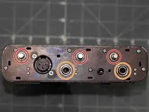
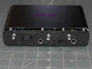
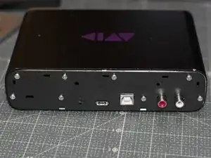
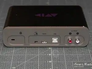
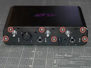
Turn the unit upside down.
-
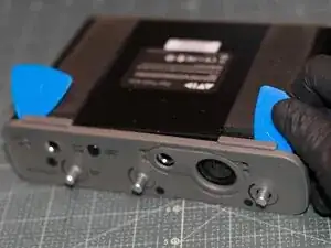
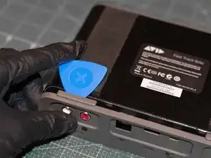
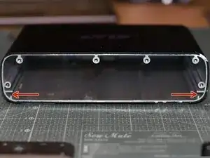
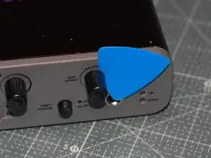
Insert an iFixit pick in the ridge between the body and the front plate, start in front of the feet pads and work around the unit.
-
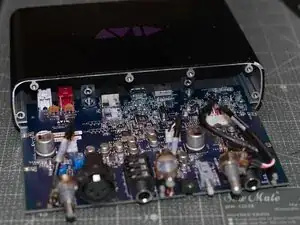
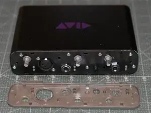
Carefully pry of the front plate.
-
-
-
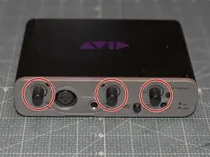
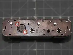
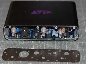
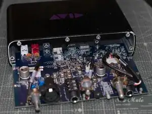
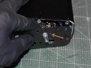
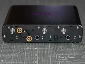
Use pliers to loosen the washers on the three potentiometer stems. The washers can then be unscrewed by hand.
-
Use pliers to loosen the washers holding the two 6.3 mm jacks. The washers can then be unscrewed by hand.
-
-
-
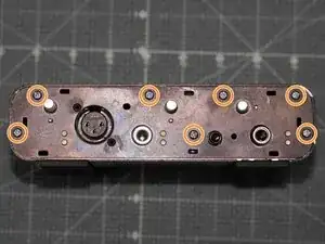
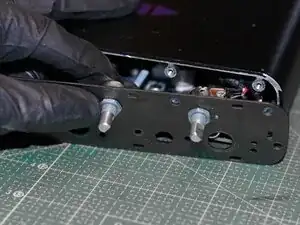
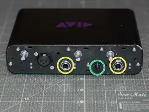
Unscrew all the screws fitted on the front plate, in the following order:
-
Use a PH1 screwdriver to remove the two PH1 screws securing the XLR jack.
-
Use a PH2 screwdriver to remove the remaining PH2 screws securing the front metal plate to the chassis.
-
-
-
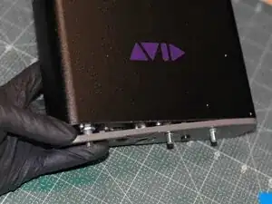
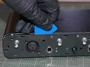
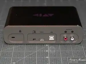
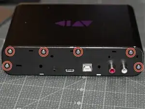
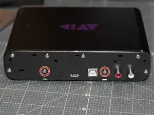
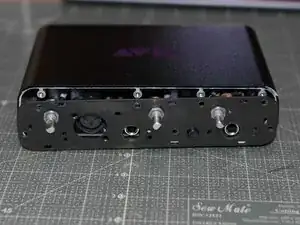
Turn the unit upside down. Face the rear of the unit.
-
Insert an iFixit pick in the ridge between the body and the back cover, start behind the feet pads and work around the unit.
-
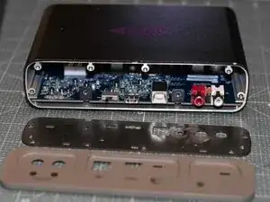
Carefully pry off the plastic rear cover.
-
-
-
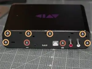
Unscrew all the screws fitted on the rear plate.
-
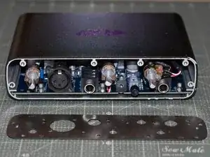
Use a PH2 screwdriver to remove the PH2 screws securing the motherboard.
-
Use a PH2 screwdriver to remove the remaining PH2 screws which are securing the rear metal plate to the chassis.
-
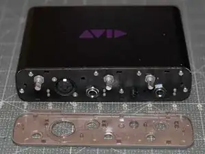
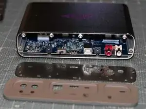
(optional) Remove the front metal plate.
-
-
-
Face the front of the unit.
-
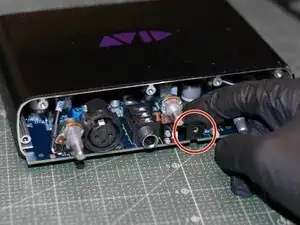
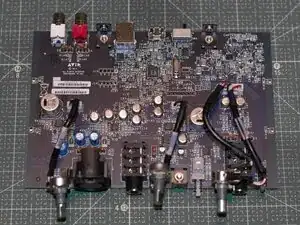
Gently pull out the motherboard by pulling the black post attached to the motherboard. The motherboard should slide out without any resistance.
-
The full teardown is now complete!
-
-
-
Face the rear of the unit.
-
Reattach the rear plate.
-
Reinsert and tighten the PH2 screws holding the rear plate to the chassis.
-
-
-
Face the front of the unit.
-
Gently insert the motherboard back into the chassis, all the way in. The motherboard is to rest on the lower lip.
-
-
-
Face the rear of the unit.
-
Reinsert and tighten the two PH2 screws securing the motherboard.
-
Reattach the plastic rear cover by pressing it on. Put pressure on the sides, and work around the unit.
-
-
-
Face the front of the unit.
-
Insert the three potentiometers into the front plate.
-
Each potentiometer has a small prong that is to be fitted through the front plate, either to the right or below the potentiometer stem.
-
Reattach and tighten the washers for the potentiometers.
-
-
-
Reinsert and tighten all screws into the front plate, in the following order:
-
Reinsert and tighten all PH2 screws securing the front plate to the chassis.
-
Reinsert and tighten the two PH1 screws securing the XLR jack into the front plate.
-
Reattach and tighten the washers for the two 6.3 mm jacks.
-
Use pliers to make sure the washers for the potentiometers and the 6.3 mm jacks all are tight and secured.
-
If the Direct Monitor button cap (between the two 6.3mm jacks) were previously removed, please reattach it by gently pressing it into place.
-
-
-
Reattach the plastic front cover by pressing it on. Put pressure on the sides, and work around the edges of the unit.
-
-
-
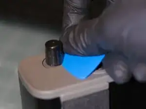
Attach all three knobs to the potentiometer stems by pressing them straight on. They are interchangeable and the knobs will only fit in one orientation on the stems.
-
Congratulations! You are now done!